


Page 16
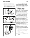
side of the valve. The pressure will be zero when the heater
is not running. When the heater is operating the manifold
gas pressure should be 4.0" wc for natural gas and 9.0" wc
for LP within .2" wc. To adjust the manifold gas pressure,
first remove the slotted cap next to the inlet pressure port
on the inlet side of the gas valve. Under the slotted cap is a
slotted plastic screw which increases the manifold pressure
when turned clockwise and decreases the manifold pressure
when turned counterclockwise. After measurements, and
adjustments if necessary, have been made, make sure to
replace the 1/8" NPT gas valve plugs on the inlet and
manifold pressure ports, and the cap on the manifold
pressure adjustment screw. It is extremely important to
replace these parts before leaving the installation. Failure to
do so can result in damage to property or injury or death.
With the heater firing, the pressure must be within the
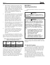
range shown in Table 7. Also check the pressure with the
heater off.
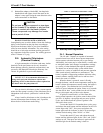
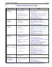
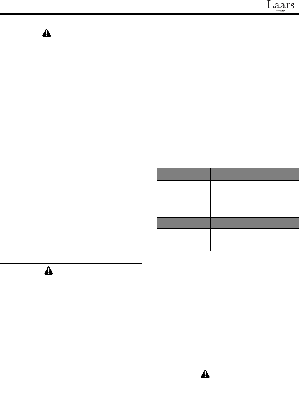
Table 7. Gas Supply Pressure Requirements
Supply Pressure Minimum Maximum
Natural Gas 6.0 Inches WC 11.0 Inches WC
(1.5 kPa) (2.8 kPa)
LP Gas 10.5 Inches WC 14.0 Inches WC
(2.7 kPa) (3.5 kPa)
Manifold Pressure Nominal
Natural Gas 4.0 Inches WC (1.0 kPa)
LP Gas 9.0 Inches WC (2.3 kPa)
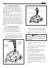
2J-4. Adjustment of Water Pressure
Switch
If the heater is installed in line with a two speed
pump, the pressure switch MUST be adjusted to prevent
the heater from firing on low-speed or low-flow pump
operation. The pressure switch is preset at the factory for
normal pool installations. Do not adjust it unless the
heater's water connections are more than three feet above
or below the pool surface. If they are not in this range, the
pressure switch must be adjusted. This can be done in the
field if the water connections are no more than six feet
above the pool surface or no more than ten feet below it.
For other situations, contact a Waterpik Technologies
representative.
The pressure switch should be adjusted to turn
the heater off when the pump is off. Setting
the switch to close at too low of a flow can
damage the appliance.
Do not operate this heater outdoors at
temperatures below 20 degrees Fahrenheit
(°F) (-7 degrees Celsius [°C]).
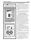
2J-2. Start-up
Confirm that pool water is flowing normally through
the pool system and equipment. Start the heater in
accordance with the Operating Instructions section of this
manual, with particular attention to the lighting and
shutdown instructions and temperature control operation.
The heater may not start on the first try. Air in the
gas line or other start-up situations may cause it to recycle.
It will lock out if ignition is not achieved in three attempts.
On the LX model heater, to provide three additional
attempts, press and release the mode button until the
indicator on the LCD screen aligns with "OFF". Now press
and release the button again until the indicator on the
LCD screen aligns with the desired setting, either "POOL"
or "SPA".
To reset the cycle on the model LT press and release
the mode button until the indicator lights for the "SPA"
and "POOL" settings are off. Then press and release it
again until the indicator light for the desired setting is
back on..
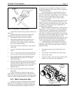
When the heater starts, immediately feel the outlet
header of the heater to confirm that there is adequate water
flow. The header should not be hot. Normally, water
temperature will rise only a few degrees as it passes
through the heater, and a hot header or pipe indicates
low water flow.
When the heater is fired for the first time, the
combustion chamber refractory binder material
is driven out by the heat of the flame. White
smoke and/or sharp odors may be emitted
from the vent during this period. Do not inhale
combustion product fumes at any time, and
especially when these fumes are being
emitted. This burn-in period will last only a
few minutes.
2J-3. Gas Pressure
Confirm that gas supply pressure is correct. If the
gas supply pressure is less than required, check for
undersized pipe between the meter and the heater, a
restrictive fitting, or an undersized gas meter. Gas supply
pressures to the heater, when it is operating, are listed in
Table 7.
The manifold pressure may be checked by
connecting a manometer to the pressure port on the outlet
WARNING
WARNING
CAUTION