


LX and LT Pool Heaters
Page 13
Note: Only the small tab of the top groove will fit behind
the upper panel.
40. Remove the button plug type washer from the left
side cover panel. This panel will not be used in
reassembling the heater after a heat exchanger
reversal. However, the button plug washer will be
needed. Do not replace the cover panel over the vent
switch outlet. Doing so may cause the heater to
malfunction.
41. The gas line may enter the heater from either the left
side or the right side. Replace the button plug washer
in the hole through which the gas line will enter the
heater.
42. Use the button plug to cover the hole on the opposite
side of the heater.
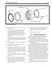
Note: Be sure that the white fiber gasket is positioned on
the top flange of the exhaust vent.
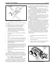
43. Replace the top. While positioning the top, pull the
control panel through the hole and place it on top of
the panel. Fasten the top to the heater by replacing
the two hex head screws at the upper corners of the
raceway and the two philips head screws at the upper
corners of the rear panel.
44. Position the vent grill over the exhaust vent. Replace
the four philips head screws that fasten the vent grill
to the top.
45. Reinstall the control panel assembly into the top
panel. Slide the back of the bezel into place, then
lower the front, aligning the holes in the bezel with
the holes in clips on the tabs on the top panel.
Replace the two philips head screws located at the
front edge of the bezel.
46. Slide the raceway cover up to the top of the heater. Be
careful not to pinch any wires. Replace the two
screws on the bottom flange to hold the cover in
place.
47. Replace the front panel (door).
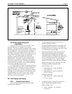
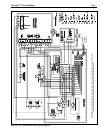
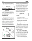
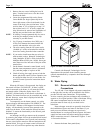
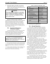
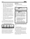
2I-2. Pool/Spa Piping Systems
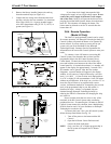
Figure 15 illustrates typical piping for pool
equipment in pool/spa combination pools. With their
electronic temperature controls, the LX and LT are
particularly suited for this type of pool installation.
The heater must be protected from back-siphoning of
water, which can result in dry starts. If there is any chance
of back-siphoning, provide a check valve between the pool
and the filter pump inlet.
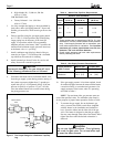
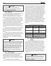
Arrangement of pool system components other than
as illustrated in these diagrams can affect the operation of
the heaters water pressure switch. Location of the heater
above or below the pool water surface can also affect
operation of the switch. In general, the pressure switch can
be adjusted to accommodate this effect if the heater water
connections are no more than six feet below the pool water
surface and no more than 15 feet above it. See instructions
for pressure switch adjustment in the heater start-up
section of this manual for more information about this.
Note that when pool equipment is located below the
pool surface a leak can result in large scale water loss or
flooding. Waterpik Technologies cannot be responsible for
such water loss or flooding or the damage caused by it.
Do not install a shutoff valve or any kind of variable
restriction in the water piping between the heater outlet
and the pool/spa.
Pool systems with water flow rates higher than 125
GPM require an adjustable external bypass at the heater.
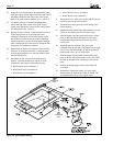
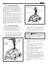
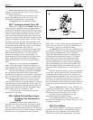
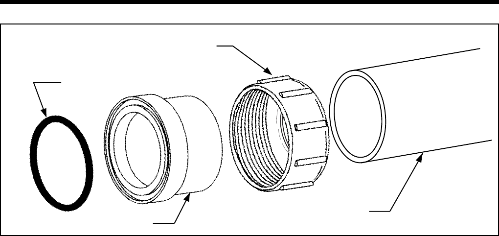
Figure 16. Piping to Heater.
O-RING
COUPLING
COUPLING NUT
PVC OR CPVC PIPE