


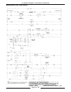
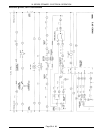
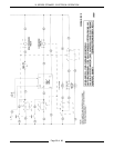
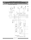

VL SERIES STEAMER - ELECTRICAL OPERATION
Pa
g
e 47 of 88
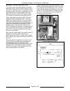
F. Once compartment temperature reaches
approximately 180°F thermal switch
closes and supplies power L1 (HOT) to:
1) Steam exhaust solenoid valve (N.O.)
ener
g
ized and closes.
NOTE: Even thou
g
h steam exhaust
solenoid valve is closed, a small openin
g
exists in the “
g
uillotine” blade of the valve
to allow “limited free ventin
g
” of
condensate durin
g
a cook cycle.
2) Pilot li
g
ht (red) comes on indicatin
g
timed cookin
g
at 180°F has started.
3) Timer motor ener
g
ized
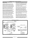
2. Cookin
g
Timer times down to approximately
one minute before zero.
A. Micro switch SW2 contacts chan
g
e state
from N.O. back to N.C. (normal startin
g
position).
1) Steam exhaust solenoid valve is de-
ener
g
ized and opens to exhaust
steam and pressure from the
compartment.
2) Steam control solenoid (trip) is
ener
g
ized and unlatches steam
control arm allowin
g
it to return to the
rear. Steam supply the compartment
is shut off.
3. Cookin
g
timer reaches zero.
A. Micro switch SW1 contacts chan
g
e state
from N.O. back to N.C. (normal startin
g
position).
B. Buzzer is ener
g
ized.
4. Cookin
g
timer is manually turned off.
5. Compartment power switch is turned OFF,
buzzer is de-ener
g
ized and power is removed
from the common side of micro switch SW1.
6. Steamer reverts to preheat cycle until:
A. A cookin
g
cycle is started. i.e.
compartment door is closed and screw
handle ti
g
htened down, time is dialed into
timer (past 5 minutes) and the
compartment power switch is turned ON.
B. Water level drops below low level cut-off
probes.
C. Power switch is turned OFF.
NOTE: Heatin
g
elements will come back on, after
the boiler pressure drops below the low pressure set
point limit (9 psi) and will stay on until the hi
g
h
pressure set point (11 psi) is reached. As lon
g
as
steam pressure is within limits, even while cookin
g
,
heatin
g
elements can
g
o off. The boiler is able to re-
pressurize to the upper set point limit even with all
compartments in cook mode.
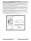
WATER REFILL (AFTER INITIAL FILL)
1. Water level drops below low level probe (LL).
A. Power is removed from terminal 7 on the
differential water level control.
1) The internal contactor coil is de-
ener
g
ized returnin
g
contacts 3 and 4
back to there ori
g
inal state and
ener
g
izin
g
the boiler fill solenoid to
refill the boiler.
2. Water reaches LL (low level) probe.
A. Power to terminal 2 on the water level
control is present but no switchin
g
occurs.
3. Water reaches HL (hi
g
h level) probe.
A. Power to terminal 10 on the differential
level control.
1) The internal contactor coil on the
differential level controls is ener
g
ized.
a. The normally closed contacts on
terminals 3 and 4 open, de-
ener
g
izin
g
the boiler fill solenoid
and the boiler stops fillin
g
.
NOTE: The internal contactor coil has a
lockin
g
path throu
g
h contacts on terminals
7 & 8 to the low level probe to keep the
coil ener
g
ized after the water level drops
below the hi
g
h level probe.
4. The water refill cycle will occur whenever the
water level is below the low level probe and will
not affect the operation of either the preheat or
cook cycle.
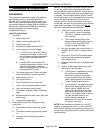
BOILER BLOWDOWN/DRAIN
1. Main power switch turned OFF.
A. Power switch indicator li
g
ht (red)
g
oes out
and power is removed form all boiler
controls except the blowdown timer.
2. Blowdown timer switch is pressed.
A. The normally open timer contacts close,
ener
g
izin
g
the blowdown solenoid valve
and the cold water condenser valve.
B. Boiler be
g
ins blowin
g
down and drainin
g
until timer “times out” after approximately
4 minutes.
C. Timer contacts re-open and power is then
removed from the blowdown solenoid
valve and the cold water condenser valve.