


VL SERIES STEAMER - SERVICE PROCEDURES AND ADJUSTMENTS
Pa
g
e 24 of 88
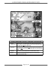
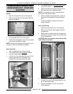
WATER LEVEL CONTROL(S)
TEST
Loose electrical connections may prevent the heat
from comin
g
on or may cause the boiler to overfill.
An accumulation of lime scale on or near the water
level sensin
g
probes may cause them to retain
water (moist) on the probe surface and
g
ive a false
readin
g
. Also, a cracked or dama
g
ed insulator may
g
ive a false readin
g
. These conditions may prevent
the boiler from fillin
g
or cause dry firin
g
. Dry firin
g
will result in dama
g
e to the heatin
g
elements on
electric models or to the boiler on
g
as or electric
models.
WARNING:
THE FOLLOWING STEPS REQUIRE
POWER TO BE APPLIED TO THE UNIT DURING
THE TEST. USE EXTREME CAUTION AT ALL
TIMES.
Solid State - Low level Cut-Off & Differential
Control
1. Turn the power switch ON.
2. Ensure that water is fillin
g
the boiler.
A. Confirm that water supply valve(s) are
turned on.
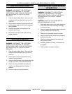
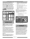
B. Observe boiler water level in the water
level
g
au
g
e. If empty, boiler should fill in
approximately 11 minutes.
3. Check the volta
g
e across terminals L1 & L2 on
the board. Meter should read 120VAC.
A. If volta
g
e is correct then the hi
g
h level
(HL) relay should ener
g
ize, closin
g
HL-3
contacts and the HL LED should li
g
ht up.
The boiler fill solenoid should then
ener
g
ize and start fillin
g
the boiler. Verify
boiler fill solenoid valve is receivin
g
120VAC and water is flowin
g
throu
g
h it.
B. If boiler fill solenoid is receivin
g
power but
no water is flowin
g
, inspect fill solenoid for
malfunction or valve for clo
gg
ed ports. If
solenoid is bad or ports can not be
cleaned, then replace boiler fill solenoid
and check for proper operation.
C. If boiler fill solenoid is not
receivin
g
power
and the electrical connections have been
checked, then the HL relay is not bein
g
ener
g
ized or the HL-3 contacts are not
closin
g
. Replace water level control board
and check for proper operation.
4. If boiler is fillin
g
properly, when the water level
reaches the low level cut-off (LLCO) probe,
LLCO relay should ener
g
ize closin
g
LLCO-2
contacts, heat source should come on
(standard models only) and LLCO LED will
li
g
ht.
5. Once the water level reaches the hi
g
h level
(HL) probe, the inverse latchin
g
relay of the
board (solid state) should ener
g
ize and lock
throu
g
h the low level probe (LL) and ILR-1
contacts. With ILR-2 contacts open, the HL
relay is de-ener
g
ized and HL LED
g
oes out.
With the HL-3 contacts open, the boiler fill
solenoid should de-ener
g
ize and stop the boiler
fill.
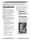
6. If water is in the boiler but is not bein
g
detected
by the water level probes, the probes may need
cleaned and/or boiler delimed. See “Water
Level Probes” as outlined below for inspectin
g
and cleanin
g
of probes and “BOILER” for a
procedure on boiler inspection, clean-out and
delimin
g
.
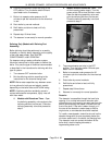
7. Turn the power switch OFF and disconnect the
lead wire from each probe. Check the probes
as outlined below.
A. With an ohmmeter, check between the
probe terminal and boiler shell. An open
circuit should be present when the boiler is
empty. If resistance is present, remove
and inspect the probes as outlined below
under “Water Level Probes”. When the
boiler is full of water, a resistance readin
g
should be measurable between the probes
and boiler.
NOTE:
The actual resistance readin
g
will depend on
water quality and probe condition.
8. After performin
g
steps 1-5A and verifyin
g
the
water level control boards operation, if the
control is not functionin
g
as described, then
replace it and check for proper operation.
Electro Mechanical - Low level Cut-Off &
Differential Control
WARNING:
THE FOLLOWING STEPS REQUIRE
POWER TO BE APPLIED TO THE UNIT DURING
THE TEST. USE EXTREME CAUTION AT ALL
TIMES.
1. Ensure that water is fillin
g
the boiler.
A. Confirm that water supply valve(s) are
turned on.
B. Observe boiler water level in the water
level
g
au
g
e.
C. Verify boiler fill solenoid valve is receivin
g
120VAC and water is flowin
g
throu
g
h it.
2. Check for correct volta
g
e bein
g
applied to the
low level and differential water level controls.
A. Turn the water supply valve off then turn
the power switch ON. Check the input
volta
g
e across terminals 1 & 2. Meter
should read 120VAC. If volta
g
e is correct
proceed to step 2B. If volta
g
e is incorrect,
find the source of the problem and repeat
this step.