


VL SERIES STEAMER - SERVICE PROCEDURES AND ADJUSTMENTS
Pa
g
e 31 of 88
D. With the thermocouple disconnected,
connect the meter leads to the tube and
threaded end. Turn the power switch ON
and li
g
ht the pilot. Hold down the
OFF/PILOT/ON knob and allow the pilot to
heat the thermocouple for one to two
minutes. Take an open
circuit readin
g
and
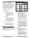
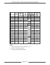
compare with the chart below.
1) If the readin
g
is less than the
minimum or thermocouple is not
operatin
g
as described, replace the
thermocouple as outlined under
“PILOT AND THERMOCOUPLE
ASSEMBLY (GAS MODELS)” in
“REMOVAL AND REPLACEMENT
OF PARTS” then check for proper
operation.
3. If after checkin
g
and/or replacin
g
thermocouple, the pilot or main burners are still
not functionin
g
properly, then a problem in the
g
as combination control valve exists as well.
Replace the combination control valve as
outlined under “GAS COMBINATION
CONTROL VALVE” in “REMOVAL AND
REPLACEMENT OF PARTS” then check for
proper operation.
NOTE: Gas combination control valves are not
serviceable and should not be disassembled. Once
you have isolated the problem to this control,
replace it. Do not
attempt to repair the assembly.
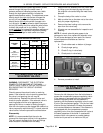
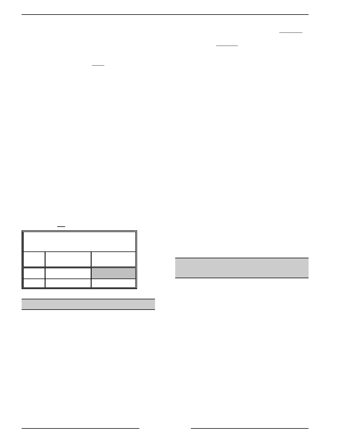
THERMOCOUPLE
DC MILLIVOLT
READINGS
CLOSED CIRCUIT
(CONNECTED)
OPEN CIRCUIT
(DISCONNECTED)
Typical 15
Range 10 - 20 20 - 35
GAS BURNERS
The main
g
as burners are located under the boiler
for heatin
g
and number five to seven dependin
g
on
the steamer model. They are made of aluminized
steel with lanced type ports and have adjustable air
shutters in the front. Fixed orifice type hoods extend
from the manifold to establish
g
as flow to each
burner.
Air Shutter Adjustment
1. I
g
nite the burners and allow to heat up for at
least five minutes.
2. Verify the manifold pressure as outlined under
“GAS MANIFOLD PRESSURE
ADJUSTMENT”.
3. Loosen the set screw on the burner bein
g
adjusted. Closin
g
the air shutter will decrease
primary air to the burner and openin
g
the
shutter will increase
primary air the burner.
4. Monitor the burner flame and set the air shutter
openin
g
as follows:
A. Open up the air shutter until the inner
portion (blue) of the flame lifts off the
burner port and then turn the air shutter
back until the flame touches the burner
port a
g
ain. A sli
g
ht tin
g
e of oran
g
e and
yellow in the flame is acceptable. An
extremely yellow flame indicates too little
primary air (oxy
g
en), producin
g
poor
burnin
g
characteristics and the heatin
g
efficiency drops off. A by product of this
would be soot (carbon).
Factory air shutter settin
g
s are: natural
gas - open approximately ½ inch;
propane gas - fully open.
5. After the air shutter adjustment is made, ti
g
hten
the set screw.
Inspection
Remove
g
as burners by liftin
g
burner up and slidin
g
it to the rear just enou
g
h to clear the
g
as orifice
hood. Lower the front end of burner and brin
g
it
forward under the
g
as manifold pipe. Inspect burner
for clo
gg
ed or dama
g
ed ports. Clean or replace as
necessary. When reinstallin
g
burners, assure that
locatin
g
pin is in the hole for proper positionin
g
and
to prevent burner from rollin
g
over.
AUTOMATIC IGNITION SYSTEMS
(GAS MODELS)
When the main power switch is turned ON and the
i
g
nition control modules reset switch is in the ON
position, the i
g
nition control module is ener
g
ized
with 24VAC between terminals five and six.
Hi
g
h volta
g
e is sent from terminal nine to the spark
electrode and an output of 24 volts is sent from
terminals two and three to the pilot coil in the
combination valve, allowin
g
g
as to flow to the pilot.
The sparkin
g
will continue for 90 seconds or until
the flame sensor has confirmed that an adequate
pilot flame is present.