


VL SERIES STEAMER - ELECTRICAL OPERATION
Pa
g
e 43 of 88
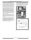
3. Water level reaches LLCO (low water level cut-
off) probe for the water level control and to the
auxiliary LLCO probe for the auxiliary low level
cut-off control.
A. Power to terminal 9 on the water level
control.
1) LLCO relay ener
g
izes, LLCO-2 (N.O.)
contacts close and LED li
g
hts.
B. Power to terminal LLCO on the auxiliary
low water level cut-off control.
1) LLCO relay ener
g
izes, LLCO-2 (N.O.)
contacts close and LED li
g
hts.
NOTE: LLCO relays will remain ener
g
ized
and LLCO LED’S will remain lit until the
water level drops below the LLCO probes
or the power switch is turned OFF.
4. Water reaches LL (low level) probe.
A. Power to terminal 2 on the water level
control is present but no switchin
g
occurs.
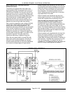
5. Water reaches HL (hi
g
h level) probe.
A. Power to terminal 6 on water level control.
1) The inverse latchin
g
relay of the
board is ener
g
ized, chan
g
in
g
the
state of ILR-1 (N.O.) and ILR-2 (N.C.)
contacts. The inverse latchin
g
relay
will remain ener
g
ized throu
g
h the
alternate latchin
g
path of ILR-1
contacts until the water level recedes
below the low level probe.
2) With ILR-2 contacts open, HL relay is
de-ener
g
ized, HL-3 (N.O.) contacts
open and HL LED
g
oes out.
3) Water fill solenoid is de-ener
g
ized.
(boiler fill time approx. 11 min.)
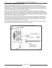
6. Manual re-set switch is pressed, ener
g
izin
g
the
coils on the hi
g
h limit and low water relays.
A. Contacts 1 & 9 on the hi
g
h pressure relay
chan
g
e state and lock from N.C. to N.O.
and turn off the hi
g
h pressure indicator
li
g
ht. Concurrently, Contacts 1 & 9 on the
low water relay chan
g
e state and lock from
N.C. to N.O. and turn off the low water
indicator li
g
ht.
B. Contacts 5 & 9 on the hi
g
h pressure relay
chan
g
e state and lock from N.O. to N.C.,
supplyin
g
power (NEUTRAL) to one side
of the auxiliary
g
as solenoid valve.
Concurrently, Contacts 5 & 9 on the low
water relay chan
g
e state and lock from
N.O. to N.C., supplyin
g
power (L1) to the
other side of the auxiliary
g
as solenoid
valve.
NOTE: For both relays to ener
g
ize, the hi
g
h
pressure switch must be closed and the water level
in the boiler must be above the low level cut-off
probes in order for LLCO-2 (N.O.) contacts to close.
C. Auxiliary
g
as solenoid valve is ener
g
ized
and opens to allow
g
as flow.
D. As lon
g
as the i
g
nition control module is
sensin
g
a pilot flame, the internal main
valve (MV) contacts close (N.O.) on the
i
g
nition control module. The main
g
as
valve is ener
g
ized and
g
as be
g
ins flowin
g
.
E. Burners li
g
ht and water in boiler be
g
ins to
heat up.
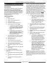
7. Boiler steam pressure reaches upper limit set
point of 11 PSI. (Approximately 15 min.)
A. Cyclin
g
pressure switch opens, main
g
as
solenoid valve de-ener
g
izes,
g
as flow
shuts off and burners
g
o out.
B. As boiler heats up and builds pressure,
some by-pass water/steam is produced
which runs into the steam drain box. This
causes the cold water condenser (CWC)
solenoid to cycle, coolin
g
the drain water.
This solenoid is powered by the CWC
thermostat.
NOTE: Steam should not be seen enterin
g
a
compartment until the manual steam control arm is
pulled forward and locked.
8. Boiler steam pressure drops below lower limit
set point of 9 PSI and the cyclin
g
pressure
switch closes.
A. Boiler steam pressure is maintained by the
cyclin
g
of the pressure switch between the
upper and lower set point limits. The
cyclin
g
pressure switch continues to
ener
g
ize and de-ener
g
ize the main
g
as
solenoid valve startin
g
and stoppin
g
the
flow of
g
as, which in turn, cycles the
burners on and off. This sequence
continues until one of the followin
g
occurs:
1) Boiler pressurizes to 15 PSI, causin
g
the hi
g
h limit pressure switch to open.
At that time, the auxiliary
g
as valve
de-ener
g
izes, shuttin
g
off the
g
as
flow to the burners and the hi
g
h limit
failure li
g
ht will come on. This li
g
ht
will stay lit until the pressure drops
below the lower limit set point of 6
PSI and the manual re-set switch is
pressed.
2) Boiler water level drops below the
LLCO probes for the water level and
the auxiliary low level cut-off controls
which then de-ener
g
izes the LLCO
relays, chan
g
in
g
the contact state of
LLCO-2 (N.O.) back to open. This de-
ener
g
izes the main and auxiliary
g
as
solenoid valves. The
g
as solenoid
valves will remain off and the low
water level li
g
ht will come on and stay
lit until the water level rises above the
LLCO probes and the manual re-set
switch is pressed.