


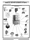
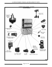
VL SERIES STEAMERS - REMOVAL AND REPLACEMENT OF PARTS
Pa
g
e 19 of 88
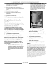
BOILER FILL AND COLD WATER
CONDENSER SOLENOID VALVES
WARNING:
DISCONNECT THE ELECTRICAL
POWER TO THE MACHINE AT THE MAIN
CIRCUIT BOX. PLACE A TAG ON THE CIRCUIT
BOX INDICATING THE CIRCUIT IS BEING
SERVICED.
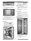
1. Turn off the water supply to the steamer.
2. Open the cabinet base doors and remove the
two screws at the top of the boiler control box
and allow cover to drop down. Both solenoid
valves are located side by side near the front of
the boiler control box with the boiler fill on the
ri
g
ht and the cold water condenser to the left.
3. Disconnect the power lead wires from the
solenoid valve bein
g
serviced.
4. Disconnect the water lines for the valve bein
g
serviced and remove the valve.
5. Reverse procedure to install.
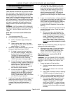
PILOT AND THERMOCOUPLE
ASSEMBLY (GAS MODELS)
WARNING:
DISCONNECT THE ELECTRICAL
POWER TO THE MACHINE AT THE MAIN
CIRCUIT BOX. PLACE A TAG ON THE CIRCUIT
BOX INDICATING THE CIRCUIT IS BEING
SERVICED.
WARNING:
SHUT OFF THE GAS BEFORE
SERVICING THE UNIT.
WARNING:
ALL GAS JOINTS DISTURBED
DURING SERVICING MUST BE CHECKED FOR
LEAKS. CHECK WITH A SOAP AND WATER
SOLUTION (BUBBLES). DO NOT USE AN OPEN
FLAME.
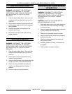
1. Open the cabinet doors to access the pilot and
thermocouple assembly. The assembly is
located to the ri
g
ht of the center burner and
half way back from the front.
2. Disconnect thermocouple and pilot
g
as supply
tubin
g
from the combination control valve.
3. Remove the two screws holdin
g
the pilot to its
bracket.
4. Replace the thermocouple or pilot assembly
and check for proper operation.
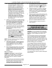
GAS COMBINATION CONTROL
VALVE
WARNING:
DISCONNECT THE ELECTRICAL
POWER TO THE MACHINE AT THE MAIN
CIRCUIT BOX. PLACE A TAG ON THE CIRCUIT
BOX INDICATING THE CIRCUIT IS BEING
SERVICED.
WARNING:
SHUT OFF THE GAS SUPPLY
BEFORE SERVICING THE UNIT.
WARNING:
ALL GAS JOINTS DISTURBED
DURING SERVICING MUST BE CHECKED FOR
LEAKS. CHECK WITH A SOAP AND WATER
SOLUTION (BUBBLES). DO NOT USE AN OPEN
FLAME.
NOTE:
Gas combination control valves are not
serviceable and should not be disassembled. Once
the problem has been isolated to this control,
replace it. Do not attempt to repair the assembly.
1. Open the cabinet base doors and remove the
two screws at the top of the boiler control box
and allow cover to drop down.
2. Disconnect electrical supply wires and conduit
runnin
g
to the combination control valve.
3. Disconnect the thermocouple lead (if
applicable), pilot
g
as supply tube from control
and pipe connections on each side of the
control.
4. Reverse procedure to install.
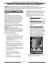
5. Set manifold pressure as outlined under “GAS
MANIFOLD PRESSURE ADJUSTMENT” in
“SERVICE PROCEDURES AND
ADJUSTMENTS”.
6. Check for proper operation.