


VL SERIES STEAMER - SERVICE PROCEDURES AND ADJUSTMENTS
Pa
g
e 34 of 88
7. Once the correct pressure has been set, turn
the power switch OFF, replace the adjustment
screw cap and 1/8 inch NPT plu
g
(pressure tap)
on the outlet side of the valve.
8. Check for proper operation.
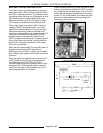
DIRECT STEAM MODELS
These models consist of a pressure re
g
ulator and
g
au
g
e that run off a buildin
g
s potable steam supply.
The re
g
ulator used will be of the adjustable type and
should be set for a dischar
g
e pressure of 10 psi. The
maximum input pressure to the re
g
ulator should be
15 psi. Incomin
g
power (120VAC) for the
compartment controls is supplied from a junction
box in the base.
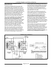
REGENERATED STEAM
(OLDER MODELS)
The steam coils on a re
g
enerated type steamer are
intended for use at a steam supply pressure of 15
psi maximum. A pressure re
g
ulatin
g
valve is
available as optional equipment for steamers where
a buildin
g
s steam supply pressure exceeds 15 psi.
The re
g
ulator used will be of the adjustable type and
should be set for a dischar
g
e pressure hi
g
h enou
g
h
for
g
ood steam
g
eneration. This pressure can be
monitored by the supplied pressure
g
au
g
e. The
re
g
ulator should be set, only when steam is flowin
g
(steam solenoid valve is open). If steam is heavy
with condensate, install a ball float trap in the steam
line before the pressure re
g
ulatin
g
valve.
WARNING:
SHUT OFF THE STEAM SUPPLY
BEFORE SERVICING THE UNIT.
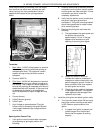
To remove a steam coil, disconnect union in steam
supply line to the coils and in the condensate
dischar
g
e line from the coils. Remove header that
supplies steam to coils by disconnectin
g
union at
each coil. In same way, remove coil condensate
collection header. Remove four bolts clampin
g
each
coil flan
g
e in place and pull coil forward. Use a new
flan
g
e
g
asket when replacin
g
coil. The faces that
mate with
g
asket must be clean.
Turn steamer power switch ON, allowin
g
steam
g
eneration and, consequently, pressure to rise to
normal operatin
g
level and then turn power switch
OFF for a final pur
g
in
g
of boiler and steam supply
lines. Steamer is now ready for use.
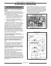
HEATER CONTACTORS
WARNING:
DISCONNECT THE ELECTRICAL
POWER TO THE MACHINE AT THE MAIN
CIRCUIT BOX. PLACE A TAG ON THE CIRCUIT
BOX INDICATING THE CIRCUIT IS BEING
SERVICED.
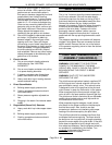
The contactor can be serviced by removin
g
the
cover of the contactor box.
A noisy contactor (hum or chatter) is
g
enerally due
to excessive dust or dirt on the armature pole faces
or around the armature core preventin
g
the ma
g
net
coil from pullin
g
the armature into a completely
sealed position. This can usually be corrected by
blowin
g
or wipin
g
the pole faces clean. To inspect
electrical contacts, remove cover at top of contactor
by removin
g
two screws which hold it in place.
Replace contactor if the electrical contacts appear
to be severely pitted or burned.
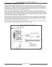
HEATING ELEMENTS
WARNING:
THE FOLLOWING STEPS REQUIRE
POWER TO BE APPLIED TO THE UNIT DURING
THE TEST. USE EXTREME CAUTION AT ALL
TIMES.
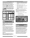
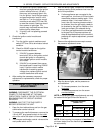
1. Measure the volta
g
e at the heatin
g
element
terminals and verify it a
g
ainst the data plate
volta
g
e.
A. If volta
g
e is incorrect, find the source of
the problem.
B. If volta
g
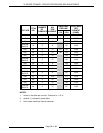
e is correct, check current draw
(amps) throu
g
h the heatin
g
element lead
wires.
See table below for proper
values.
C. If current draw is correct then heatin
g
element is ok.
D. If current draw is not correct then replace
the element and proceed to step 3.
NOTE:
When replacin
g
an element, always use a
new
g
asket and ensure that the flan
g
e and tube
surfaces which contact the
g
asket are clean. If
removed element shows a pronounced scale
build-up on its heatin
g
tubes, the other elements
should be removed and mechanically cleaned to
remove the scale. This will prolon
g
their life. DO
NOT immerse elements in a chemical solution to
descale.
2. Check for proper operation.