


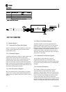
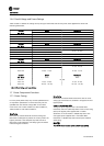
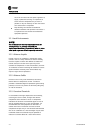
Contactor Drive Mode OFF Bypass
Mode
Test Mode
M1 Closed Open Open Closed
M2 Closed Open Open Open
M3 Open Open Closed Closed
Table 1.1 Contactor Operation
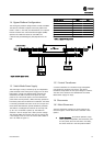
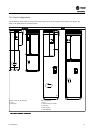
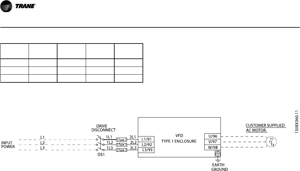
Figure 1.1 Basic Non Bypass Circuit
1.3 Bypass Options
1.3.1 Common Run/Stop with Bypass
Allows a remote signal to initiate operation in either drive
control or bypass depending upon the position of the
bypass selector switch.
1.3.2 Automatic Bypass
This feature automatically transfers the motor from drive to
bypass without operator intervention when a fault
condition trips the drive, after a programmable time-out
period. The VFD’s internal fault circuitry controls this
action. The time delay permits all automatically resettable
faults to clear prior to transfer to bypass. Run permissive or
safety circuit signals override the auto bypass function and
may prevent or delay bypass operation.
1.3.3 Run Permissive in Bypass
With run permissive active, the drive sends a run request
and waits for a remote response before commanding the
motor to start. The response indicates the system is safe to
operate.
1.3.4 Basic Fire Mode in Bypass
This option switches the panel to bypass whenever a
remote fire mode signal is given to the VFD through the
input terminals. In either drive or bypass, fire mode is
intended to ignore common safety and overload inputs for
emergency situations. The motor will continue to run in
bypass until fire mode is removed or the drive, panel, or
motor fails. External safety signals and motor overload are
ignored when in fire mode.
1.3.5 Advanced Fire Mode in Bypass
The advanced fire mode allows for a variety of
programmable responses to an external fire mode
command signal. Bypass options are programmed through
the drive’s fire mode parameters. See 6.1.13 ECB Advanced
Fire Mode.
1.3.6 Overload Protection
This thermally activated device provides mechanical
overload protection for the motor while in bypass
operation. It measures motor current and is set to the full
load amps (FLA) of the motor. A 1.2 x FLA service factor is
built-in and maintained, meaning that should the motor
current increase above that value, the overload will
calculate the level of increase to activate timing for the trip
function. The higher the current draw, the quicker the trip
response. The overload provides Class 20 motor protection.
Introduction
1-2 BAS-SVX49A-EN