


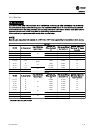
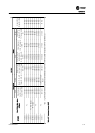
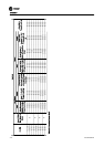
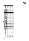
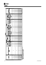
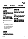
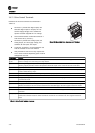
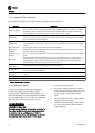
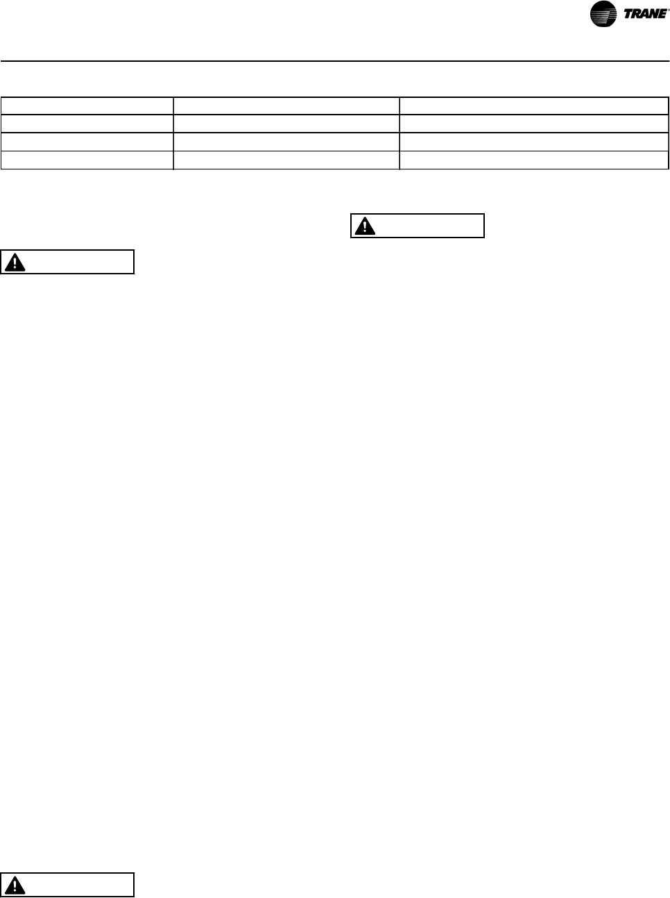
Field Connection Tightening Torque lb-in (N-m) Temperature & Type Rating
L1, L2, L3/Ground 25 (2.8) 25 (2.8) Use 75
°
C Copper Conductor
2T1, 2T2, 2T3/Ground 25 (2.8) 25 (2.8) Use 75
°
C Copper Conductor
TB1 25 (2.8) 25 (2.8) Use 75
°
C Copper Conductor
Table 3.15 Sample Tightening Torque and Wire Rating Label
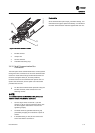
3.4.6 Input Line Connection
WARNING
Hazardous Voltage!
Disconnect all electric power, including remote disconnects
before servicing. Follow proper lockout/tagout procedures
to ensure the power cannot be inadvertently energized.
Failure to disconnect power before servicing could result in
death or serious injury.
CAUTION
RUN INPUT POWER, MOTOR WIRING AND CONTROL
WIRING IN THREE SEPARATE METALLIC CONDUITS OR
RACEWAYS FOR HIGH FREQUENCY NOISE ISOLATION.
FAILURE TO ISOLATE POWER, MOTOR AND CONTROL
WIRING COULD RESULT IN LESS THAN OPTIMUM DRIVE
AND ASSOCIATED EQUIPMENT PERFORMANCE.
•
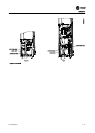
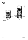
Connect 3-phase AC input power wire to
terminals L1, L2, and L3. See the connection
drawing inside the cover of the unit.
•
Depending on the configuration of the
equipment, input power may be connected to a
circuit breaker or disconnect switch.
•
Torque terminals in accordance with the
information provided inTable 3.11 and Table 3.13
on the label inside the panel cover.
•
Use with Isolated Input Source. Many utility
power systems are referenced to earth ground.
Although not as common, the input power may
be an isolated source. All drives may be used
with an isolated input source as well as with
ground reference power lines.
3.4.7 Motor Wiring
WARNING
Hazardous Voltage!
Disconnect all electric power, including remote disconnects
before servicing. Follow proper lockout/tagout procedures
to ensure the power cannot be inadvertently energized.
Failure to disconnect power before servicing could result in
death or serious injury.
WARNING
INDUCED VOLTAGE!
Run output motor cables from multiple drives separately.
Induced voltage from output motor cables run together
can charge equipment capacitors even with the equipment
turned off and locked out. Failure to run output motor
cables separately could result in death or serious injury.
NOTE!
Run input power, motor wiring and control wiring in three
separate metallic conduits or raceways for high frequency
noise isolation. Failure to isolate power, motor and control
wiring could result in less than optimum drive and
associated equipment performance.
CAUTION
RUN INPUT POWER, MOTOR WIRING AND CONTROL
WIRING IN THREE SEPARATE METALLIC CONDUITS OR
RACEWAYS FOR HIGH FREQUENCY NOISE ISOLATION.
FAILURE TO ISOLATE POWER, MOTOR AND CONTROL
WIRING COULD RESULT IN LESS THAN OPTIMUM DRIVE
AND ASSOCIATED EQUIPMENT PERFORMANCE.
Installation
BAS-SVX49A-EN 3-25