


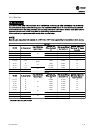
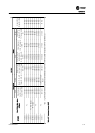
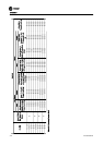
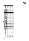
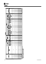
3.4.3 Wire Size
WARNING
ELECTROCUTION AND FIRE HAZARDS WITH IMPROPERLY INSTALLED AND GROUNDED FIELD WIRING!
Improperly installed and grounded field wiring poses FIRE & ELECTROCUTION hazards. To avoid these hazards, you MUST
follow requirements for field wiring installation and grounding as described in the National Electrical Codes (NEC) and your
local/state electrical codes. All field wiring MUST be performed by qualified personnel.
Failure to follow these requirements could result in death or serious injury.
NOTE!
Make all power connections with minimum 60 or 75°C/140 or 155°F rated copper wiring for installations in North America.
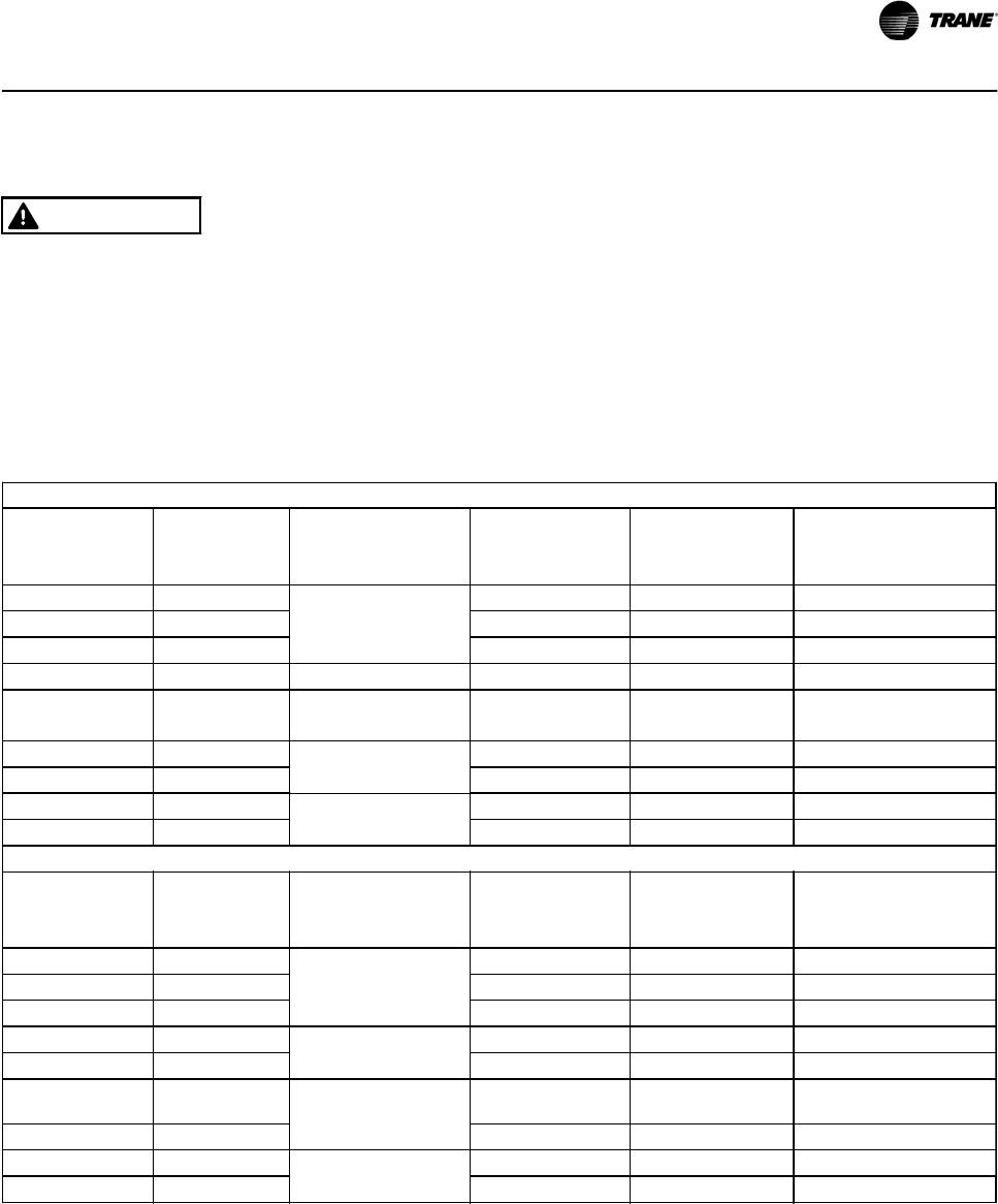
208 V AC
HP (KW) UL Motor Current
Panel (TR200) Non
Bypass & Bypass
Maximum Field
Wiring Size Class B
or C
Field Ground Wiring
Size Class B or C
Minimum Temperature
Wire Rating "
°
C" Copper
Conductor
7.5 (5.5) 24.2
P2
8 AWG 10 AWG 60
10 (7.5) 30.8 8 AWG 10 AWG 60
15 (11) 46.2 4 AWG 10 AWG 60
20 (15) 59.4 P3 3 AWG 10 AWG 60
25 (18.5) 74.8
P3 - Non Bypass P4 -
Bypass
2 AWG 8 AWG 60
30 (22) 88
P4
2 AWG 8 AWG 60
40 (30) 114 1/0 AWG 6 AWG 75
50 (37) 143
P5
3/0 AWG 6 AWG 75
60 (45) 169 4/0 AWG 6 AWG 75
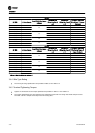
230 VAC
HP (KW) UL Motor Current
Panel (TR200) Non
Bypass & Bypass
Maximum Field
Wiring Size Class B
or C
Field Ground Wiring
Size Class B or C
Minimum Temperature
Wire Rating "Degree C"
Copper Conductor
7.5 (5.5) 22
P2
10 AWG 10 AWG 60
10 (7.5) 28 8 AWG 10 AWG 60
15 (11) 42 6 AWG 10 AWG 60
20 (15) 54
P3
4 AWG 10 AWG 60
25 (18.5) 68 3AWG 8 AWG 60
30 (22) 80
P4
3 AWG 8 AWG 60
40 (30) 104 1 AWG 6 AWG 75
50 (37) 130
P5
2/0 AWG 6 AWG 75
60 (45) 154 3/0 AWG 6 AWG 75
Table 3.9 Wire Size Chart, 208 and 230 V
Installation
BAS-SVX49A-EN 3-19