


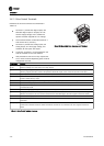


4.1.1 Inspection Prior to Start Up
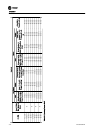
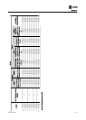
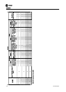
Before applying power to the unit, inspect the entire installation as detailed in Table 4.1.
Inspect For Description
Auxiliary equipment
Look for auxiliary equipment, switches, disconnects, or input fuses/circuit breakers that may reside on input
power side of drive or output side to motor. Examine their operational readiness and ensure they are ready in
all respects for operation at full speed. Check function and installation of pressure sensors or encoders (etc.)
used for feedback to drive. Remove power factor correction caps on motor, if present.
Cable routing
Ensure that input power, motor wiring, and control wiring are in three separate metallic conduits for high
frequency noise isolation. Failure to isolate power, motor, and control wiring could result in less than optimum
drive and associated equipment performance.
Control wiring
Check for broken or damaged wires and connections. Check the voltage source of the signals, if necessary. The
use of shielded cable or twisted pair is recommended for serial communication. Ensure the shield is terminated
correctly.
EMC considerations Check for proper installation with regard to electromagnetic capability.
Environmental
conditions
See panel label for the maximum ambient operating temperature. Humidity levels must be less than 95% non-
condensing. Attitude less than 3300 feet.
Fusing and circuit
breakers
Check that all fuses are inserted firmly and in operational condition and that all circuit breakers are in the open
position.
Grounding
The panel requires a dedicated ground wire from its chassis to the building ground. It is required that the
motor be grounded to the panel chassis. The use of conduit or mounting of the panel to a metal surface is not
considered a suitable ground. Check for good ground connections that are tight and free of oxidation. Run
insulated motor ground wire back to panel in conduit with motor wires.
Input and output
power wiring
Check for loose connections. Check for proper fusing or circuit breakers.
Panel interior
Panel interior must be free of dirt, metal chips, moisture, and corrosion. Check for harmful airborne contam-
inates such as sulfur based compounds.
Proper Cooling
Clearance
Panels require top and bottom clearance adequate to ensure proper air flow for cooling. See Figure 3.2 and
Figure 3.3
Switches Ensure that all switch and disconnect settings are in the proper position.
Vibration Look for any unusual amount of vibration the equipment may be subjected to when mounting panel.
Table 4.1 Inspection prior to Startup
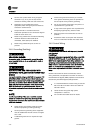
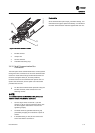
4.1.2 Start Up Procedure
In the following procedures, changing the equipment
between drive mode and bypass mode is required.
Changing modes is different for the ECB and EMB2. The
ECB uses pushbuttons on the drive keypad while the EMB2
uses a selector switch on the front of the panel. Be familiar
with the operation of these devices prior to start up.
WARNING
HAZARDOUS VOLTAGE!
The panel contains dangerous voltages when connected to
line voltage. Installation, start-up and maintenance should
be performed only by qualified personnel. Failure to
perform installation, start-up and maintenance by qualified
personnel only could result in death or serious injury.
1. Perform pre-startup procedure.
2. Ensure that all operator devices are in the OFF
position. The main disconnect switch on the front
of the electromechanical bypass panel must be in
the OFF position. The panel door should be
closed.
3. Keep main disconnect switch in the OFF position
and apply voltage to the panel.
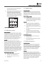
4. Confirm that input line voltage is balanced within
3%. If not, correct the input voltage imbalance
before proceeding.
Start Up
4-2 BAS-SVX49A-EN