


3 Installation
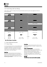
3.1.1 Tools Required
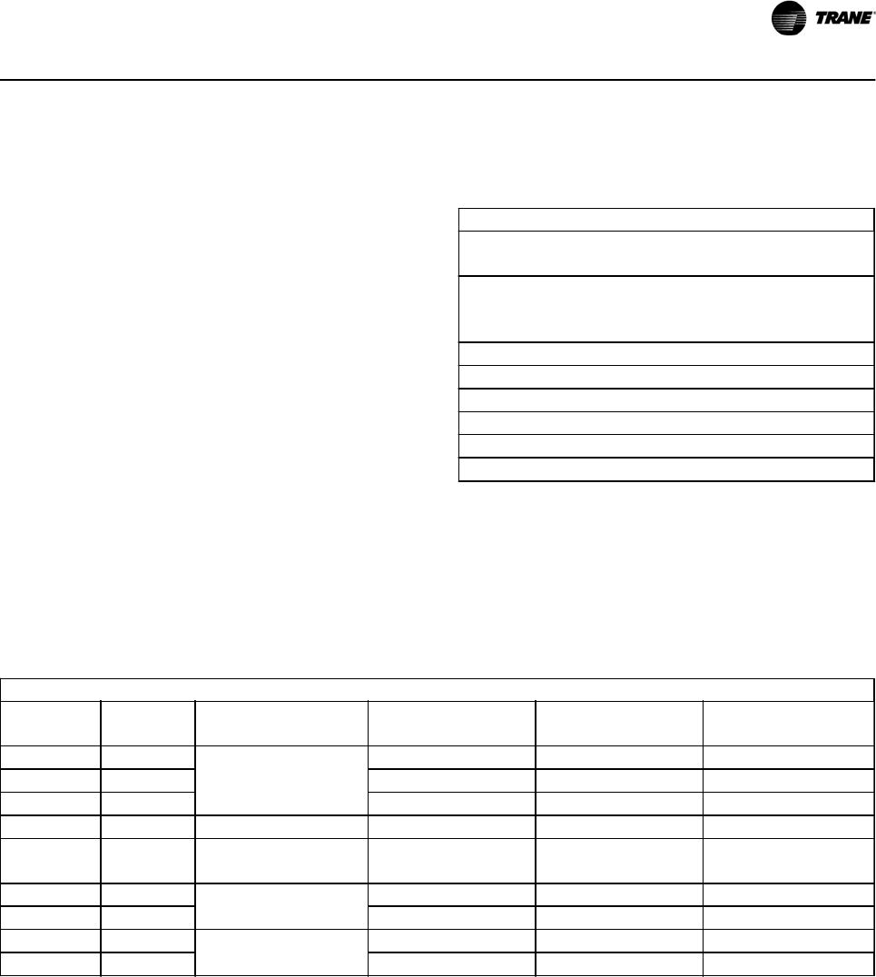
In addition to the standard tool kit, the tools in Table 3.1
are recommended for installation of the option panel.
TOOLS
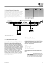
Spreader bar capable of lifting up to 750 lbs.
Max diameter 0.5 in.
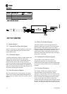
Forklift, crane, hoist or other lifting device capable of handling
up to 750 lbs. (Qualified device operator available for operating
the equipment.)
Metric Socket Set: 7 - 19mm
Socket Extensions: 4, 6, and 12 inch
Torx driver set: T10 - T40
Torque wrench: 6 - 375 lbs-in
Allen Wrenches:1/8, 3/16, 1/4, & 5/16 inches
Metric or English wrenches: 7 - 19mm
Table 3.1 Tools Required
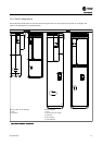
3.1.2 Drive Fuses
To maintain UL, the drive fuses should be replaced only with the fuses specified in , , , and . If an alternate drive fuse is
desired please consult the factory. See the specifications label inside the cover of the unit for acceptable replacement drive
fuses. A sample of this data can be seen in Table 3.6
208 V AC
HP (KW)
UL Motor
Current
Panel (TR200) Non Bypass
& Bypass
Main Fuse (TR200)
Bussman
Drive Fuse (TR200)
Bussman
Transformer Fuse (TR200)
Bussman
7.5 (5.5) 24,2
P2
LPJ-40-SP JJN-50
10 (7.5) 30,8 LPJ-50-SP JJN-50
15 (11) 46,2 LPJ-70-SP JJN-60
20 (15) 59,4 P3 LPJ-90-SP JJN-80
25 (18.5) 74,8
P3 - Non Bypass P4 -
Bypass
LPJ-125-SP JJN-125
30 (22) 88
P4
LPJ-150-SP JJN-125
40 (30) 114 LPJ-175-SP JJN-150
50 (37) 143
P5
LPJ-250-SP JJN-200 FNQ-R-1.25
60 (45) 169 LPJ-250-SP JJN-250 FNQ-R-1.25
Table 3.2 Drive Fuses 208 V
Installation
BAS-SVX49A-EN 3-1