


5.1.2 EMB2 Auto Bypass
General Information
Auto bypass allows a fault condition in the drive to
activate running the motor in bypass without operator
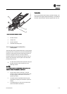
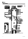
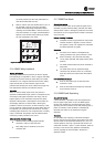
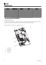
intervention. Activation of the function is through setting
DIP switches (S100) located on the EMB2 bypass control
card (see Figure 5.1). A fault condition enables a delay
timer prior to tripping the drive into bypass. The fault trip
and running in bypass are reported as output from the
bypass control card. The auto bypass function is built in.
Prior to Enabling Auto Bypass
•
Complete the start-up procedure to verify that
the motor rotation direction in bypass is correct
and that the system is ready in all respects for
continuous full speed operation in bypass.
WARNING
HAZARDOUS VOLTAGE!
Remove power to the bypass panel before setting auto
bypass dip switch settings. Bypass can contain high
voltage. Failure to remove power to bypass panel before
setting dip switches could result in death or serious injury.
Operation
•
With the bypass selector switch in drive and auto
bypass enabled, a fault signal from the drive will
activate the auto bypass timer.
•
If the fault clears before the time delay is
complete, the motor remains operating in drive
mode. This allows temporary faults, such as a
momentary under or over voltage, to clear
without transferring the system to bypass.
•
If the timer completes its cycle before the fault
clears, the panel trips into bypass mode and the
motor runs at constant full speed from line input
voltage.
•
In bypass, the motor will stop if safety or motor
overload conditions are exceeded.
•
Once auto bypass is activated, the only way to
reset the unit back to drive is by operator
intervention. Ensure that the fault has been
cleared, then rotate the bypass switch to the OFF
position momentarily before setting it back to the
drive position. This resets the drive and fault
timer.
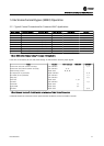
Auto Bypass Function Setup
Enable auto bypass by closing one or more DIP switches
on switch S100 located on the bypass control card. (Times
are approximate.)
•
All OFF = no auto bypass operation
•
Switch 1 only ON = 30 sec. delay
•
Switch 2 only ON = 60 sec. delay
•
Switch 3 only ON = 300 sec. delay (maximum)
•
Switch 4 = Always OFF
5.1.3 EMB2 Common Run/Stop
General Information
The common run/stop function provides remote run and
stop control of the motor in bypass. Without common run/
stop, the motor would automatically run at full speed
whenever the bypass is activated. The remote signal
provides drive control as well as bypass control, making
this one input common to both. Common run/stop is
enabled by factory default. When used with the run
permissive function, common run/stop permits run request
operation in bypass.
Prior to Enabling Common Run/Stop
•
Complete the start-up procedure to verify motor
rotation direction in bypass is correct and that
the system is ready in all respects for continuous
full speed operation in bypass.
Operation
•
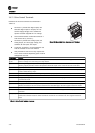
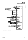
A user supplied remote start command wired to
connector X55, terminals 3 and 4 initiates remote
bypass operation. With common run/ stop,
bypass mode cannot be activated by hand on the
drive keypad or by serial communication.
Common Run/Stop Setup
•
Wire input terminals 3 and 4 on connector X55
per the system application.
To Disable Common Run/Stop
•
Common run/stop is enabled by factory default
when ordered.
•
To disable the feature, turn switch four on dip
switch S105. This allows the bypass to start when
the bypass switch is placed in the bypass
position.
•
Remove wire from terminal 18 of the drive
control terminal and insulate the end of the wire
to prevent shorting. This is required or the drive
will always have a run command.
•
If applicable, connect remote run/stop input to
terminals 12 and 18 on the drive control card.
Electromechanical Bypass (EMB2) Operation
BAS-SVX49A-EN 5-3