


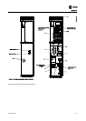
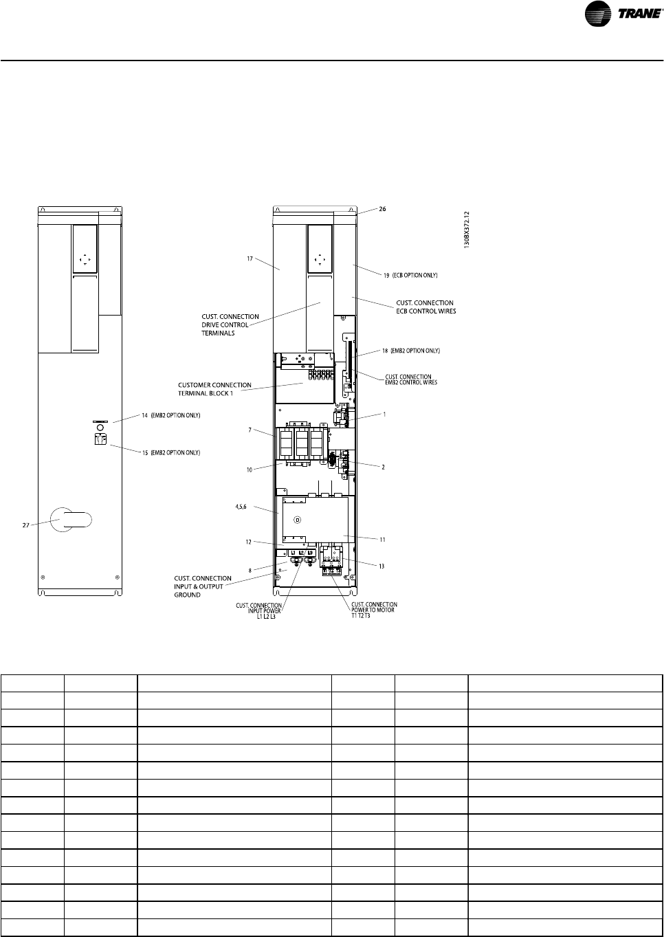
3.4.1 Component Identification & Customer Connection
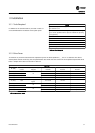
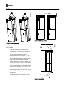
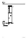
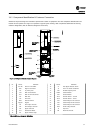
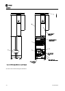
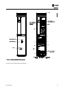
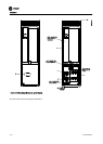
Mechanical layout drawings are intended to provide the installer or equipment user with component identification and
location for that specific unit. Figure 3.5 represents a typical layout drawing. Table 3.8 provides definitions for drawing
reference designators. (Not all reference designators are shown.)
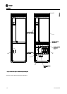
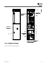
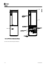
Figure 3.5 P2 Bypass Mechanical Layout Diagram
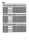
ID Device Definition ID Device Definition
1 24 V DC Panel 24 V DC SMPS 15 S1 Auto Bypass Selector Switch
2 HPC High Pot Connector 16 TF 120 V AC control transformer
3 F13 T1 primary fuse 17 VFD Variable frequency drive
4 CB1 Main Circuit Breaker 18 EMB2 Control Module
5 DS1 Main or Drive Disconnect 19 ECB Control Module
6 F15 Main fuse 20 TB1-C Terminal block 1 - Control
7 F16 Drive fuse 21 TB1-P Terminal block 1 - Power
8 GND Ground terminal 22 PR1 Control Relay for M1 Contactor
9 keypad keypad 23 PR2 Control Relay for M2 Contactor
10 M1 Drive Input contactor 24 PR3 Control Relay for M3 Contactor
11 M2 Drive Output contactor 25 UVM Under voltage module
12 M3 Bypass contactor 26 TC Top Cover
13 OL1 Overload for Motor 27 DH Disconnect Handle
14 PL1 Bypass indicator light
Table 3.8 Reference Designator Definitions
Installation
BAS-SVX49A-EN 3-7