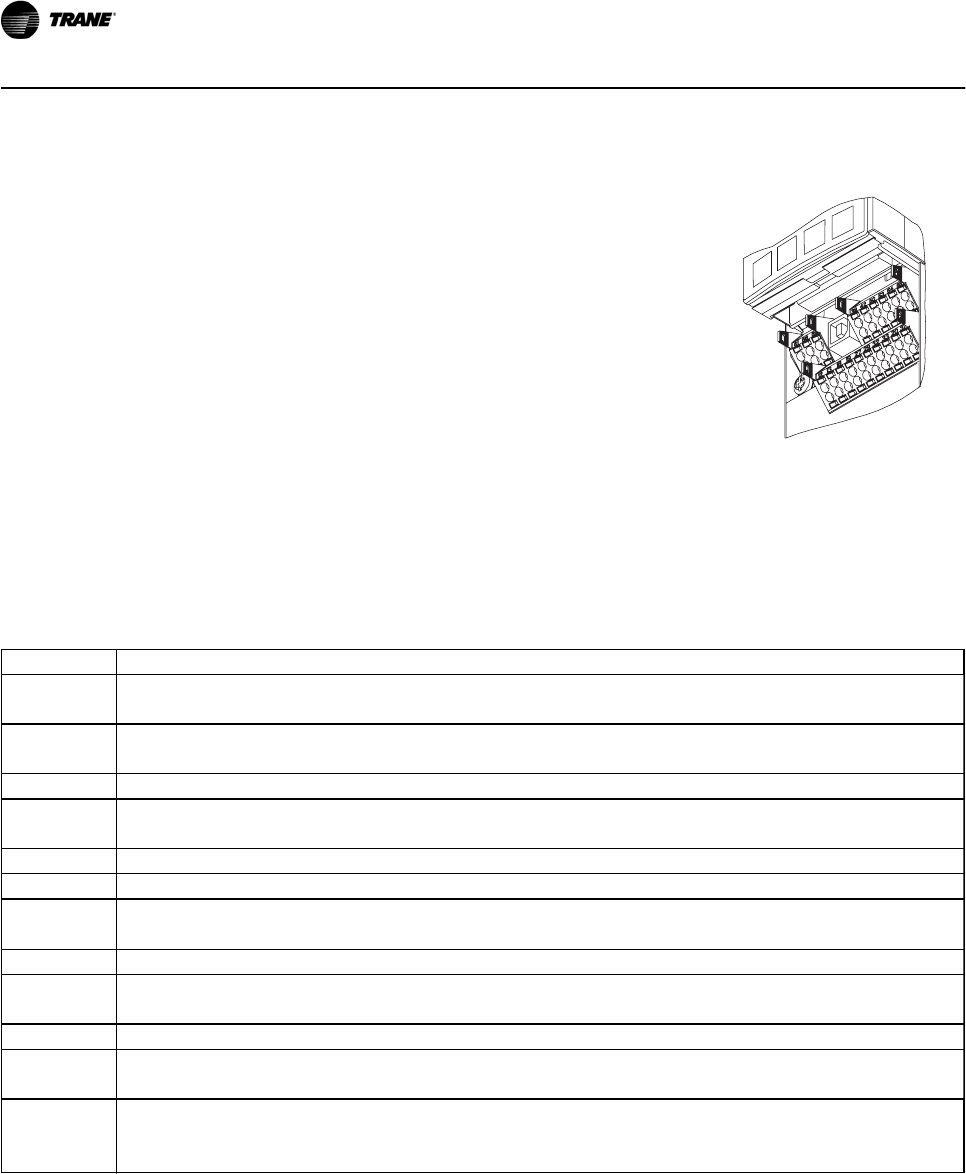
3.4.11 Drive Control Terminals
Definitions of the drive terminals are summarized in
Table 3.16.
•
Connector 1 provides four digital inputs; two
selectable digital inputs or outputs, 24 V DC
terminal supply voltage, and a common for
optional customer supplied 24 V DC voltage.
•
Serial communications use EIA-485 connector 2
with terminal 68 (+) and 69 (-).
•
Connector 3 provides two analog inputs, one
analog output, 10 V DC supply voltage, and
commons for the inputs and output.
•
A USB port, connector 4, is also available for use
with the available on the Trane website.
•
Also provided are two Form C relay outputs that
are in various locations depending upon the drive
configuration and size.
130BX231.10
Figure 3.20 Removable Drive Connectors and Terminals
Terminal No. Function
01, 02, 03, 04,
05, 06
Form-C relay output. Useable for AC or DC voltage and resistive or inductive loads. See drive support materials for
details on voltage and current ratings and relay location.
12, 13 24 V DC digital supply voltage. Useable for digital inputs and external transducers. To use the 24 V DC for digital input
common, program parameter 5-00 for PNP operation. Maximum output current is 200 mA total for all 24V loads.
18, 19, 32, 33 Digital inputs. Selectable for NPN or PNP function in parameter 5-00. Default is PNP.
27, 29 Digital inputs or outputs. Programmable for either. Parameter 5-01 for terminal 27 and 5-02 for 29 selects input/output
function. Default setting is input.
20 Common for digital inputs. To use for digital input common, program parameter 5-00 for NPN operation.
39 Common for analog output.
42 Analog output. Programmable for various functions in parameter 6-5*. The analog signal is 0 to 20 mA or 4 to 20 mA at
a maximum of 500
Ω
.
50 10 V DC analog supply voltage. 15 mA maximum commonly used for a potentiometer or thermistor.
53, 54 Analog input. Selectable for voltage (0-10 V) or current (0- or 4-20 mA). Closed is for current and open is for voltage.
Switches are located on the drive control card behind the removable keypad. See drive support materials for details.
55 Common for analog inputs.
61 Common for serial communication. Do not use to terminate shields. See drive support materials for proper shield
termination.
68 (+), 69 (-) RS-485 interface. When the drive is connected to an RS-485 serial communication bus, a drive control card switch is
provided for termination resistance. ON for termination and OFF for no termination. See drive support materials for
details.
Table 3.16 Drive Control Terminals Functions
Installation
3-28 BAS-SVX49A-EN


