


RT-PRC001-EN12
Selection
Procedure
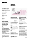
Dehumidification Selection
Determine normal unit cooling and
heating capacities as previously
described in the selection procedures on
prior page.
Typical 20 ton YFD241C
6400 cfm Total Supply airflow
2560 cfm Outside Air (40%)
3840 cfm Return Air
1.00” External Static Pressure
OA Conditions
Part load day and raining
68°F db
67°F wb
66.5 dp
95% RH
RA’ conditions
75°F db
63°F wb
52% RH
55.9 dp
Step 1: Determine the mixed/
entering air condition (MA’)
MA’ = (% outside air*outside air dry-bulb
temperature) + (% return air*return air
dry-bulb temperature)
MA’ = (0.40*68°F) + (0.60*75°F)
MA’ = 72.20°F db
Note: Repeat for wet-bulb
temperature (wb).
Plot on psychrometric chart.
MA’
72.2°F db
64.7°F wb
Step 2: Determine the additonal
static pressure drop for a reheat unit
Table PD-36 shows a static pressure drop
of 0.35” for the reheat coil and an
additional .04 for the mandatory 2”
pleated filters required when ordering the
dehumidification option. Total static
pressure =
1.0+0.035+0.04=1.075
(
≅1.1 for manual calculations)
Do not forget to also add any additional
static from other accessories.
Table PD-29 (airflow table for 20 ton
dehumidification units) indicates that a
standard motor and drive is needed for
this airflow and static pressure range.
Step 3a: Determine leaving
evaporator temperature (SA’)
Leaving Unit Temperature = SA’
Utilizing the manual selection method as
previously described and the formula
∆Temp = gross sensible or latent cooling
capacity in Bth
(cfm)(1.085)
Subtract your sensible ∆ temp from the
entering db and latent ∆ temp from the
entering wb or use the TOPSS™
program determine the leaving
evaporator temperature (temperature
without the addition of fan heat).
51.74 db
51.03 wb
Step 3b: Determine leaving
unit
temperature in standard cooling
mode
Repeat Step 3a substituting net sensible
or latent capacity for gross sensible or
latent capacity to find the leaving unit
temperature including fan heat or refer to
your TOPSS selection.
53.6 db
51 wb
84% RH
49% dp
Step 4: Determine reheat
temperature rise
Using the leaving
evaporator temp (SA’),
go to PD-37 and determine the reheat
temperature rise for that particular cfm:
17.55°F db
Note: Reheat temperature rise is based
on supply airflow and leaving
evaporator coil temperature.
Chart C-1
Step 5: Determine leaving unit
sensible temperature
with reheat
active (SA)
Reheat temperature (obtained in step 4)
+ (SA’ + fan heat) = SA
(SA’ + fan heat) = leaving unit
temperature in standard cooling mode
from step 3b.
17.55°F db + 53.6°F = 71.2°F db
SA=71.2°F
Since reheat adds only sensible heat,
follow the psychrometric chart to find the
new wb temperature.
wb
≅ 58.7°F
Consider Chart C-1. If the space relative
humidity is equal to or above the space
relative humidity setpoint, the
Dehumidification option will:
• Energize compressor or both
compressors (2 stage compressor units).
• Hot gas reheat valve is energized and
hot gas is diverted to the reheat coil.
• Dehumidification/reheat is terminated
when space humidity is reduced to 5%
below relative humidity setpoint.
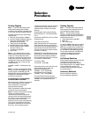
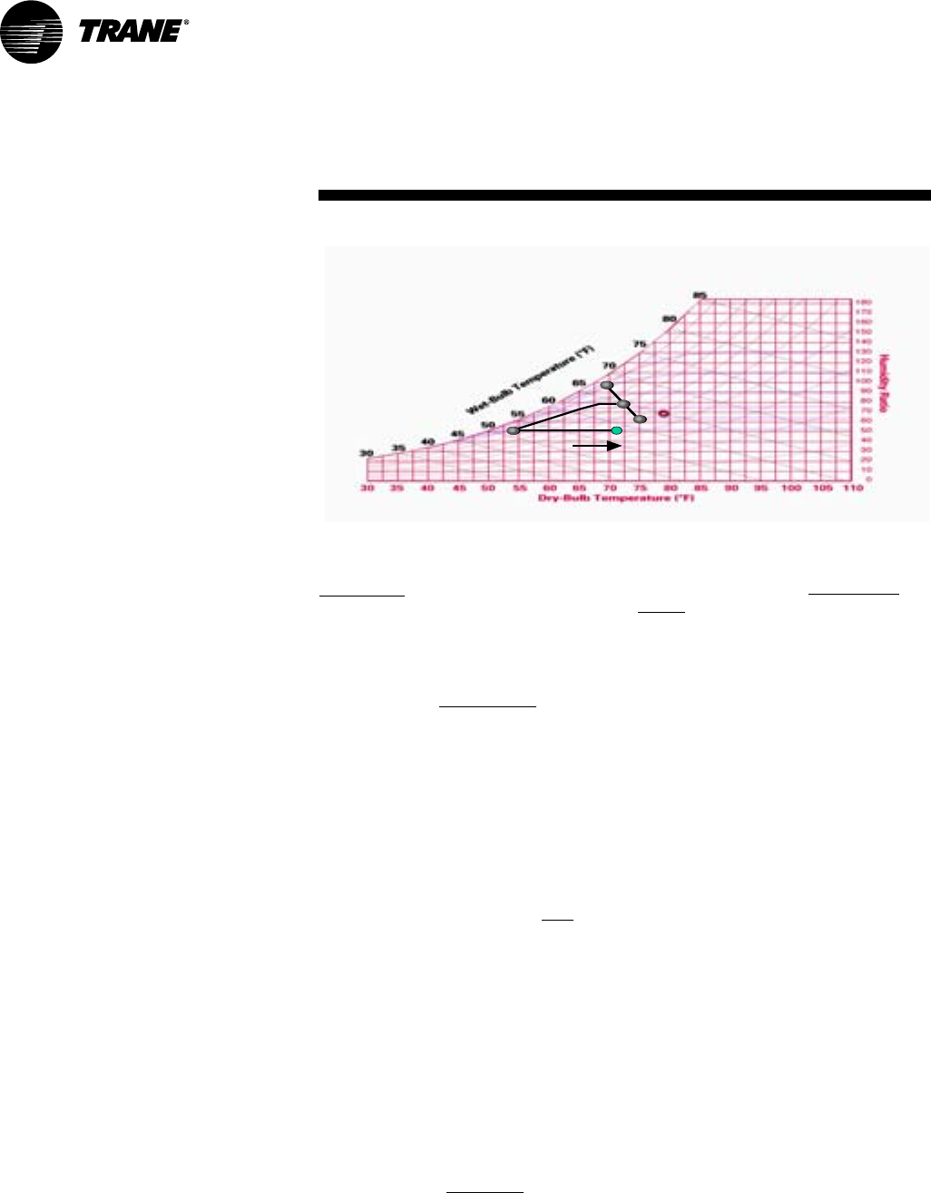
At MA’, air enters the RTU. The RTU filters,
cools, and dehumidifies the air as it
moves through the evaporator coil. Air
leaves the evaporator coil saturated at
the preset dew point condition (SA’) and
is reheated by the hot gas reheat coil to
deliver 71°F (SA) supply air to the space.
MA
MA
SA’
SA’
RA
RA
OA
OA
OA
OA
RA
68°F DB,
67°F WB
75°F DB,
52% RH
MA
72°F DB
65°F WB
SA’
51.7°F DB,
51.0°F DB
REHEAT
SA
SA
SA
71°F DB,
59°F WB