


79
CN03
CN02
CN01
5V
MCU
EEPROM
Remote controller
Indoor control
P.C. board
Power
transformer
Terminal
block
(A.B)
AC14V
AC220-
240V
Optional communication P.C. board
Remote
controller
communication
circuit
5V
power
supply
Network address
setup switch
Indoor unit
AI-NET
communication
circuit
Central control
remote controller
Terminal
block
(X.Y)
Network
Communication
units: Total 64 units
Communication
distance: 1km
CN41
CN309
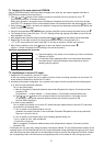
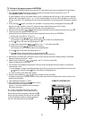
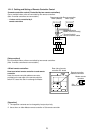
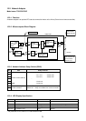
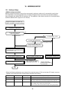
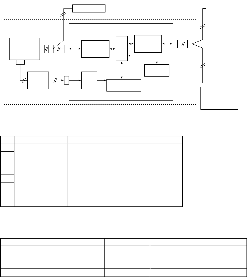
12-2. Network Adapter
Model name: TCB-PCNT20E
12-2-1. Function
A network adapter is an optional P.C. board to connect the indoor unit to AI net (Central control remote controller).
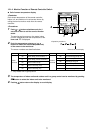
12-2-2. Microcomputer Block Diagram
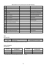
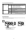
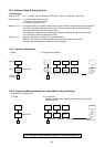
12-2-3. Network Address Setup Switch (SW01)
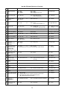
No.
1
2
3
4
5
6
7
8
Item
LSB
Central control address
MSB
Setup availability from
remote controller
Setup contents
123456
: No.1 unit : Switch OFF
: No.2 unit : Switch OFF
:
: No.63 unit
: No.64 unit
Switch OFF : Setup available from remote controller
Switch ON : Setup unavailable from remote controller
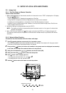
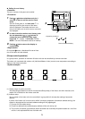
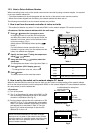
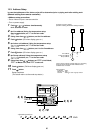
12-2-4. LED Display Specification
LED No.
D01 (Red)
D02 (Red)
D03 (Red)
D04 (Red)
Function
Communication status: Remote controller
Communication status: Center
Operation status of air conditioner
Air conditioner error
Go on
During communication
During communication
Running
Error
Go off
No communication (including communication error)
No communication (including communication error)
Stop
Normal
* For positions of LED, refer to P.C. board external view.