


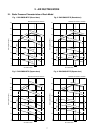
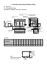
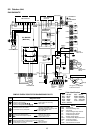
13
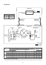
Standard
Cooling Overload
Low load
Standard
Heating Overload
Low load
Pressure
(MPa) (kg/cm²G)
Pd Ps Pd Ps
3.1 0.9 31.9 8.9
3.6 1.0 37.1 10.4
0.9 0.7 9.1 7.1
2.3 0.6 23.6 6.2
3.3 1.2 33.2 11.8
1.7 0.2 16.4 1.8
Pipe surface temperature (°C)
Discharge Suction
Indoor heat
Outdoor heat
exchanger exchanger
(TD) (TS) (TC) (TE)
85 15 10 50
93 20 15 57
20735
71 1 39 3
78 20 54 19
110 –20 26 –22
Compressor
revolutions per
second (rps)
*
74
72
28
84
47
110
Indoor
fan
HIGH
HIGH
LOW
HIGH
LOW
HIGH
Indoor/Outdoor
temp. conditions
(DB/WB) (°C)
Indoor Outdoor
27/19 35/–
32/24 43/–
18/15.5 –5/–
20/– 7/6
30.– 24/18
15/––20/
(70%)
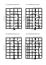
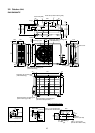
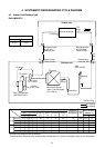
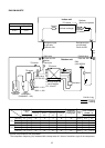
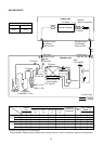
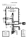
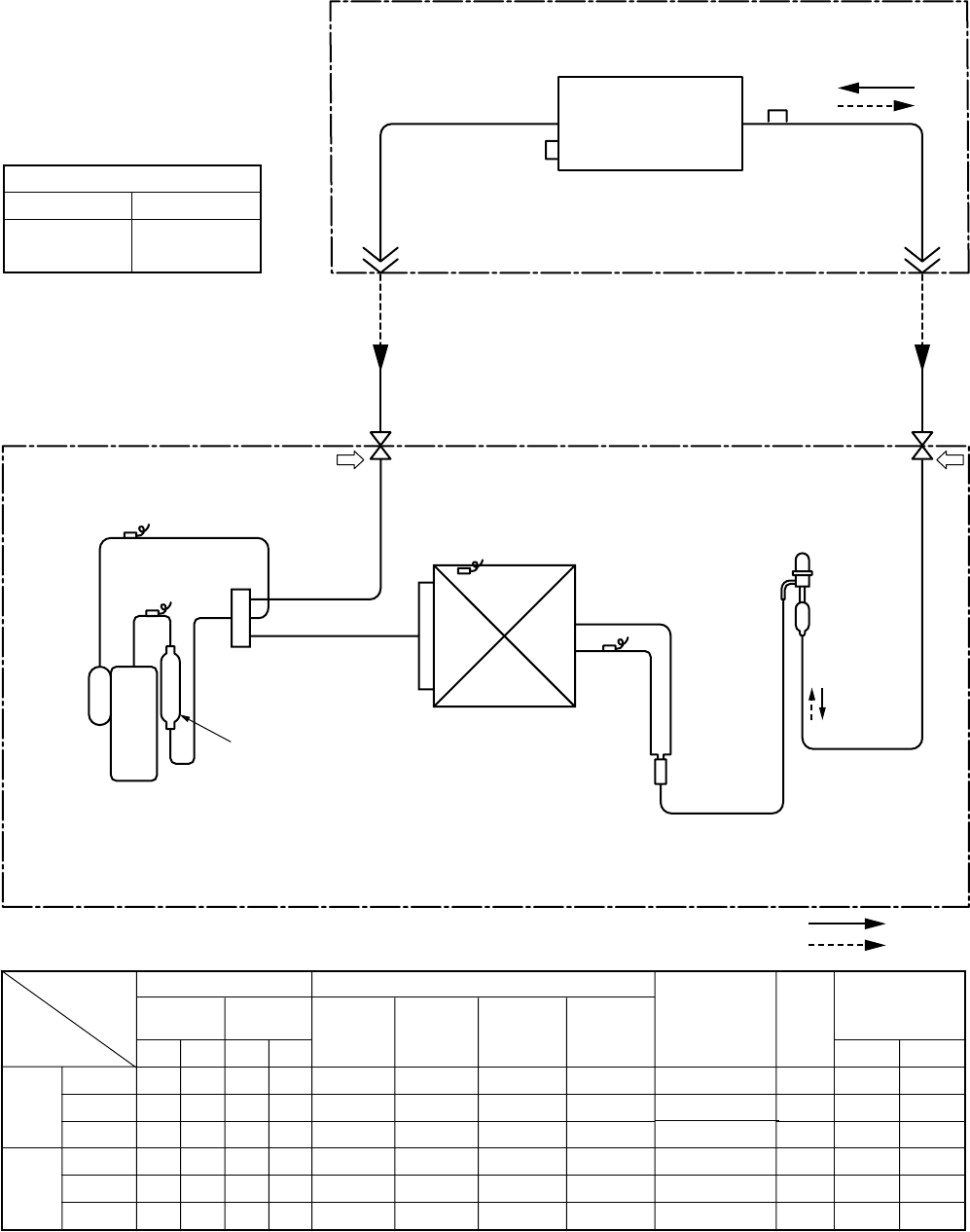
4. SYSTEMATIC REFRIGERATING CYCLE DIAGRAM
4-1. Indoor Unit/Outdoor Unit
RAV-SM561BT-E
*
4 poles are provided to this compressor.
The compressor frequency (Hz) measured with a clamp meter is 2 times of revolutions (rps) of the compressor.
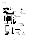
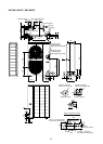
Indoor unit
Outdoor unit
Outer diameter of refrigerant pipe
Gas side ØA Liquid side ØB
12.7mm 6.4mm
TCJ
sensor
Air heat exchanger
Strainer
TC sensor
Refrigerant pipe
at gas side
Outer dia. ØA
Refrigerant pipe
at liquid side
Outer dia. ØB
Packed valve
Outer dia. ØA
Pd PsPacked valve
Outer dia. ØB
Max.
30m
TS sensor
TD sensor
TO sensor
TE
sensor
Distributor
4-way valve
(VT7101D)
Muffler
Ø19 × L160
Rotary compressor
(DA130A1F-23F)
Heat exchanger
Ø8 multiple thread
ripple 1 row 22 stages
FP1.3 flat fin
PMV
(SKV-18D26)
R410A 0.9 kg
Cooling
Heating