


77
UNIT
SET
CL
UNIT No.
SET DATA
R.C. No.
4
2
1 2 3 4
31
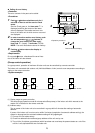
<Operation procedure>
Returned to usual display
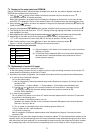
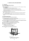
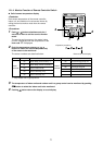
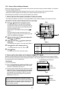
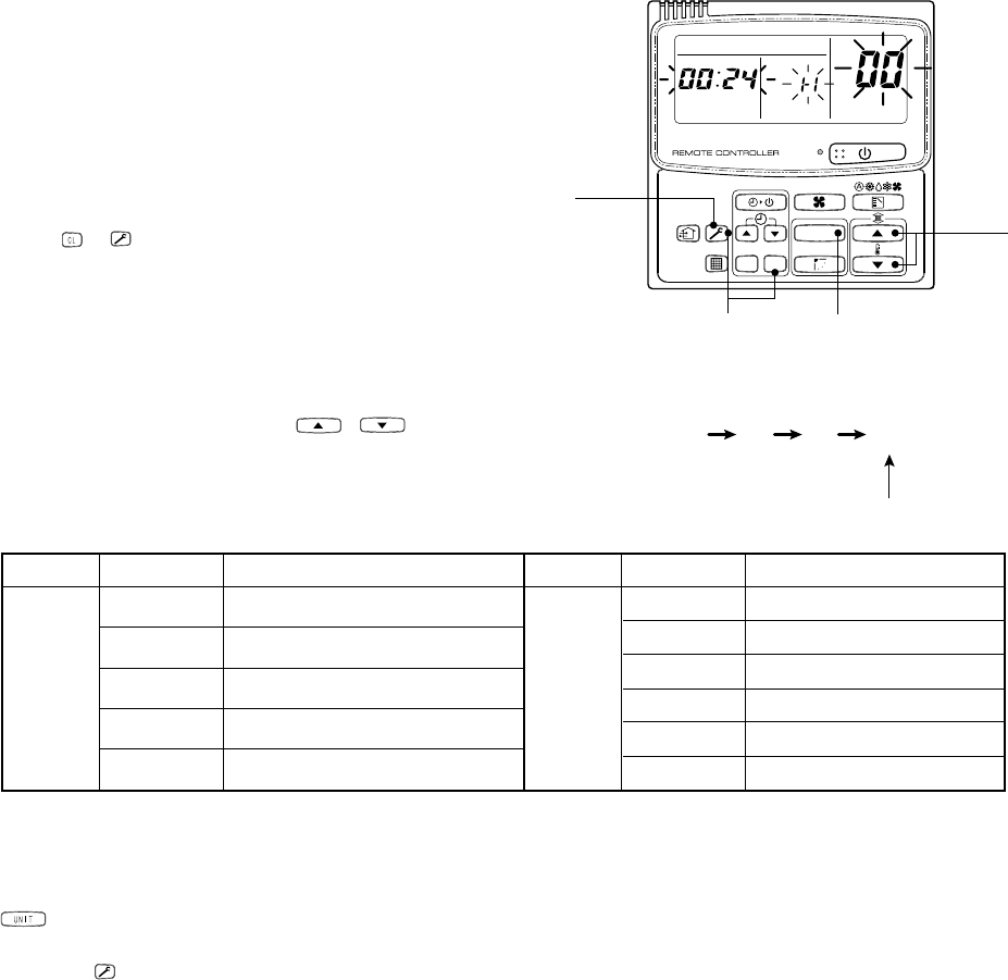
12-1-4. Monitor Function of Remote Controller Switch
n Call of sensor temperature display
<Contents>
Each sensor temperature of the remote controller,
indoor unit, and outdoor unit can become known by
calling the service monitor mode from the remote
controller.
<Procedure>
1
Push + buttons simultaneously for 4
seconds or more to call the service monitor
mode.
The service monitor goes on, the master indoor
unit No. is displayed, and then temperature of the
item code 00 is displayed.
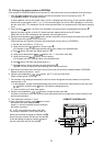
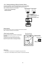
2
Push the temperature setup /
buttons to select the sensor No. (Item code)
of the sensor to be monitored.
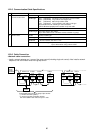
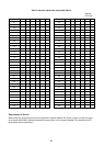
The sensor numbers are described below:
*1 Only master unit in group control
3
The temperature of indoor units and outdoor unit in a group control can be monitored by pushing
button to select the indoor unit to be monitored.
4
Pushing button returns the display to usual display.
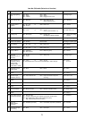
Indoor
unit data
Item code
00
01
02
03
04
Data name
Room temp (under control) *1
Room temp (remote controller)
Indoor suction temp
Indoor coil temp (TCJ)
Indoor coil temp (TC)
Outdoor
unit data
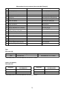
Item code
60
61
62
63
64
65
Data name
Heat exchanger temp TE
Outside temp TO
Discharge temp TD
Suction temp TS
—
Heat sink temp THS