


–8–
SMMS-i
Installation Manual
EN
SMMS-i
Installation Manual
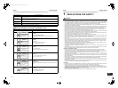
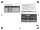
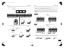
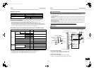
• Anchor bolt positions are as shown below:
(Unit: mm)
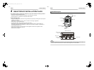
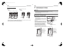
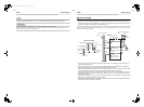
4. Mount the vibration-proof rubber (including vibration-proof blocks) so that it fits under the whole clamping leg.
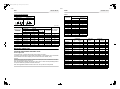
Model type A B
MAP080*, MAP1000*, MAP120* 700 990
MAP1404*, 1604* 920 1210
2. When drawing out the refrigerant pipe from the
underside, set the height of the stand to 500mm or
more.
3. Do not use 4 stands on the corner to support the
outdoor unit.
A A A
B
755
790
Continuous hole
(15 x 20 long hole)
310 or
more
310 or
more
500mm or more
NO GOOD GOOD
GOOD GOOD
NO GOOD NO GOODNO GOOD
Anchor bolt
Vibration-proof rubber
Install the vibration-proof
rubber so that the bent part
of the fixing leg is
grounded.
The bent part of the
fixing leg is not
grounded.
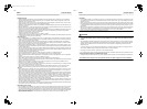
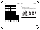
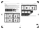
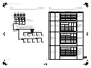
5. Be careful of the connecting arrangement of the header unit and follower units. Set the outdoor units in order of
capacity from the one with the largest capacity. (A (Header unit) ≥ B ≥ C ≥ D)
• Be sure to use a header unit for the leading outdoor unit to be connected to the main pipe. (Figure 1 and 3)
• Be sure to use a T-shaped branch joint (RBM-BT14E/RBM-BT24E: separately purchased) to connect each
outdoor unit.
• Be careful of the direction of the Outdoor unit connection piping kit for the liquid side. (As shown in Figure 2, a
Outdoor unit connection piping kit cannot be attached so that the refrigerant of the main pipe flows directly into
the header unit.)
Liquid piping
Gas piping
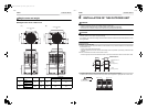
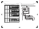
• When attaching a Y-shaped branch unit for the gas side, attach it level with the ground (Be sure not to exceed
±15 degrees.). Regarding a T-shape branch joints for the liquid side, there is no restriction for its angle.
▼ Figure 1 ▼ Figure 2
[Inverse connection of a gas-side branch unit]
▼ Figure 3 ▼ Figure 4
GOOD
Header unit
A
Follower unit
B
Follower unit
C
Main pipe
To the indoor unit
NO GOOD
Header unit
A
Follower unit
B
Follower unit
C
Main pipe
To the indoor unit
NO GOOD
GOOD
Header unit
A
Follower unit
B
Follower unit
C
Main pipe
To the indoor unit
Extension valve
NO GOOD
Header unit
A
Follower unit
B
Follower unit
C
To gas-side branch
unit
Main pipe
To the indoor unit
A
B
Within ±15 degrees
(Horizontal line)
Within ±15
degrees
(Horizontal line)
(A arrow view)
At a level position
(B arrow view)
Do not connect
a branch unit
vertically.
15-EN 16-EN
+00EH99871699_01EN.book Page 8 Thursday, August 26, 2010 4:41 PM