


–22–
SMMS-i
Installation Manual
EN
SMMS-i
Installation Manual
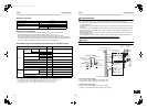
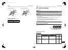
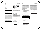
Regulation of high frequency wave
This equipment complies with IEC 61000-3-12 provided that the short-circuit power Ssc is greater than or equal to Ssc (*1)
at the interface point between the user’s supply and the public system. It is the responsibility of the installer or user of the
equipment to ensure, by consultation with the distribution network operator if necessary, that the equipment is connected
only to a supply with a short-circuit power Ssc greater than or equal to Ssc (*1)
Furthermore, when similar equipment or other equipment which may cause harmonic current emissions are to be
connected to the same interface point with this equipment, to reduce the risk of possible problems which may be caused
from addition of those harmonic current emissions, it is recommended to make sure that the short-circuit power Ssc at the
interface point is greater than the sum of the minimum Ssc required by all the equipment which will be connected to the
interface point.
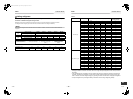
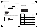
Ssc (*1)
Model Ssc (kVA)
MMY-MAP0804HT8(Z)(ZG)-E
MMY-MAP0804T8(Z)(ZG)-E
1004
MMY-MAP1004HT8(Z)(ZG)-E
MMY-MAP1004T8(Z)(ZG)-E
1290
MMY-MAP1204HT8(Z)(ZG)-E
MMY-MAP1204T8(Z)(ZG)-E
1560
MMY-MAP1404HT8(Z)(ZG)-E
MMY-MAP1404T8(Z)(ZG)-E
1692
MMY-MAP1604HT8(Z)(ZG)-E
MMY-MAP1604T8(Z)(ZG)-E
1942
9 ADDRESS SETTING
On this unit, it is required to set the addresses of the indoor units before starting air conditioning.
Set the addresses following the steps below.
CAUTION
• Be sure to complete the electric wiring before setting the addresses.
• If you turn on the outdoor unit before turning on the indoor units, the CODE No. [E19] is indicated on the 7-
segment display on the interface P.C. board of the outdoor unit until the indoor units are turned on. This is not a
malfunction.
• It may take up to ten minutes (normally about five minutes) to address one refrigerant line automatically.
• Settings on the outdoor unit are required for automatic addressing. (Address setting is not started simply by
turning on the power.)
• Running the unit is not required for address setting.
• The addresses can be set manually.
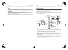
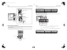
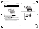
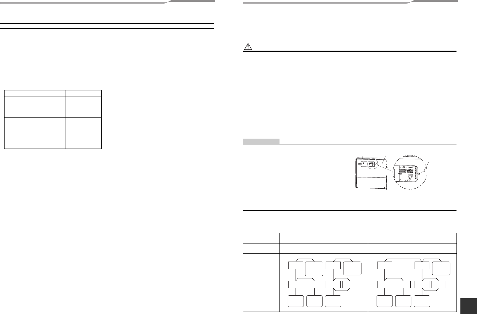
REQUIREMENT
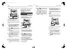
• High voltage parts exist in the electrical control box.
If you set addresses on an outdoor unit, operate the
unit through the access door shown on the illustration
on the right to avoid electric shock. Do not remove the
cover of electrical control box.
* After finishing operations, close the access door cover
and fix it with the screw.
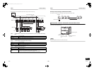
Automatic address setting
Automatic addressing: setting addresses using SW15 on the interface P.C. board on the header outdoor unit
Manual addressing:
setting addresses on the wired remote controller.
* When setting an address manually, the wired remote controller must temporarily be
paired with an indoor unit one-to-one. (when the system is organized for group
operation and no Remote controller)
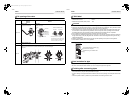
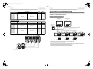
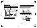
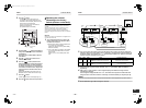
No central control: go to Address setting procedure 1
Central control of 2 or more refrigerant lines: go to Address setting procedure 2
(Example)
When controlling a single refrigerant line
centrally
When controlling 2 or more refrigerant lines
centrally
Address setting
procedure
To procedure 1 To procedure 2
System wiring
diagram
Access
door cover
Fixing screw for the
access door cover
Cover of the electrical
control box
Outdoor
Indoor
Indoor
Indoor
Indoor
Outdoor
Central
remote
controller
Central
remote
controller
Remote
controller
Remote
controller
Remote
controller
Outdoor
Indoor
Indoor
Indoor
Indoor
Outdoor
Central
remote
controller
Remote
controller
Remote
controller
Remote
controller
43-EN 44-EN
+00EH99871699_01EN.book Page 22 Thursday, August 26, 2010 4:41 PM