


SMMS-i
Installation Manual
SMMS-i
Installation Manual
–25–
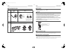
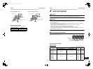
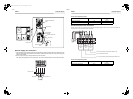
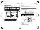
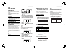
Switch setting (setting example when
controlling 2 or more refrigerant lines
centrally)
Outdoor units (setting manually)
*The items in bold font must be set manually.
Outdoor unit’s interface
P.C. board
Header unit Follower unit Header unit Follower unit Header unit Factory default
SW13, 14
(Line (system) address)
1
(No setting
required)
2
(No setting
required)
3 1
Dip switch 2 of SW30
(Terminator of indoor/
outdoor communication
line and central control
line)
ON
(No setting
required)
Set to OFF
after setting
addresses.
(No setting
required)
Set to OFF
after setting
addresses.
ON
Relay connector
Connect after
setting
addresses.
Open
Connect after
setting
addresses.
Open
Connect after
setting
addresses.
Open
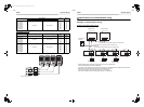
Line (system) address 1 1 2 2 3
Indoor unit address 1 2 1 2 1
Group address 0 0 1 2 0
A
U1U2
U3U4 U3U4 U3U4 U3U4 U3U4
U5U6 U1U2 U5 U6 U1U2 U5U6 U1U2 U5 U6 U1U2
U1U2 U1U2 U1U2 U1U2 U1U2
U5U6
BAB ABAB AB
Central
control
controller
Relay
connector
Relay
connector
Relay
connector
Header unit
Header unit
Header unit
Follower unit
Follower unit
Remote
controller
Remote
controller
Remote
controller
Remote
controller
Individual
Group
Indoor units
(automatic setting)
CAUTION
Relay connector connection
Never connect relay connectors between the [U1, U2] and [U3, U4] terminals before completing address setting of all
the refrigerant lines. Otherwise, the addresses cannot be set correctly.
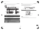
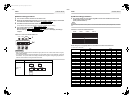
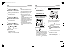
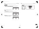
Manual address setting using the remote controller
Procedure when setting indoor units’ addresses first under the condition that indoor wiring has been completed and
outdoor wiring has not been started (manual setting using the remote controller)
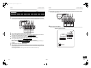
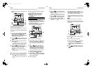
▼Wiring example of 2 refrigerant lines
In the example above, disconnect the remote controller connections between the indoor units and connect
a wired remote controller to the target unit directly before address setting.
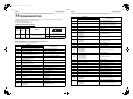
Pair the indoor unit to set and the remote controller
one-to-one.
Turn on the power.
1 Push and hold the , , and buttons at
the same time for more than 4 seconds.
LCD starts flashing.
Line (system) address 1 1 1 2 2
Indoor unit address 1 2 3 1 2
Group address
1
Header unit
2
Follower unit
2
Follower unit
2
Follower unit
2
Follower unit
Outdoor
unit
Outdoor
unit
Remote
controller
Indoor unit 1
Indoor unit 2
Indoor unit 3
Indoor unit 1
Indoor unit 2
Refrigerant line 1
Refrigerant line 2
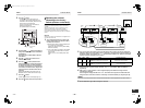
ON / OFF
TEMP.
TIME
SET CL
FILTER
RESET
TEST
TIMER SET
CODE No.
UNIT No.
SETTING
DATA
SET
R.C. No.
11
4, 7, 10
2, 5, 8
3, 6, 9
1
SET DATA
CODE No.
SET
CL
TEST
49-EN 50-EN
+00EH99871699_01EN.book Page 25 Thursday, August 26, 2010 4:41 PM