


–14–
SMMS-i
Installation Manual
EN
SMMS-i
Installation Manual
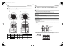
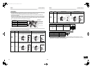
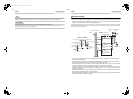
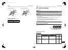
◆System restriction
◆Cautions for installation
• Set the outdoor unit first connected to the bridging pipe to the indoor units as the header unit.
• Install the outdoor units in order of their capacity codes: A (header unit) ≥ B ≥ C ≥ D
• When connecting gas pipes to indoor units, use Y-shaped branching joints to keep pipes level.
• When piping to outdoor units using Outdoor unit connection piping kits, intersect the pipes to the outdoor unit
and those to indoor units at a right angle as shown in figure 1 on “6. INSTALLATION OF THE OUTDOOR UNIT”.
Do not connect them as in figure 2 on “6. INSTALLATION OF THE OUTDOOR UNIT”.
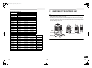
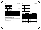
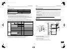
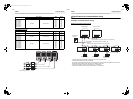
◆Allowable length and allowable height difference of refrigerant piping
*1: Farthest outdoor unit from the first branch: (D), farthest indoor unit: (j)
*2: If the total capacity of outdoor units is 46HP or more, make the equivalent length 70m (real length 50m) or less.
*3: Make the difference 65m or less if the height difference between outdoor and indoor units (H1) is more than 3m.
*4: Make the difference 50m or less if the height difference between indoor units (H2) is more than 3m.
*5: Make the difference 30m or less if the height difference between indoor units (H2) is more than 3m.
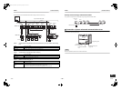
Outdoor unit combination Up to 4 units
Total capacity of outdoor units Up to 48 HP
Indoor unit connection Up to 48 units
Total capacity of indoor units
(varies depending on the height difference between
indoor units.)
H2 ≤ 15m 135% of outdoor units’ capacity
15m < H2 105% of outdoor units’ capacity
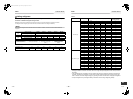
Item
Allowable
value
Pipes
Pipe length
Total extension of
pipe (liquid pipe,
real length)
Less than 96kW
Less than 34HP or
less
300m
LA + LB + La + Lb + Lc + Ld + L1 + L2 + L3 + L4
+ L5 + L6 + L7 + a + b + c + d + e + f + g + h + i + j
96kW or more 34HP or more 500m
Farthest piping length L (*1)
Equivalent length 235m
LA + LB + Ld + L1 + L3 + L4 + L5 + L6 + j
Real length 190m
Main piping length
Equivalent length 120m (*2)
L1
Real length 100m (*2)
Farthest equivalent piping length from the first branch Li
(*1)
90m (*3) L3 + L4 + L5 + L6 + j
Farthest equivalent piping length between outdoor units L0
(*1)
25m LA + LB + Ld (LA + Lb, LA + LB + Lc)
Maximum equivalent piping length of pipes connected to
outdoor units
10m La, Lb, Lc, Ld
Maximum real length of pipes connected to indoor units 30m a, b, c, d, e, f, g, h, i, j
Maximum equivalent length between branching sections 50m L2, L3, L4, L5, L6, L7
Height
difference
Height between outdoor and indoor
units H1
Upper outdoor
units
70m (*4) –
Lower outdoor
units
40m (*5) –
Height between indoor units H2 40m –
Height between indoor units H3 5m –
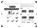
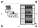
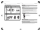
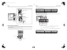
Airtightness test
After the refrigerant piping has been finished, execute an airtight test.
For an airtight test, connect a nitrogen gas canister as shown in the figure on the next page and apply pressure.
• Be sure to apply pressure from the service ports of the packed valves (or ball valves) at the liquid side, gas side
and balance pipe side.
• An airtight test can only be performed at the service ports at the liquid side, gas side and balance pipe side on
header unit.
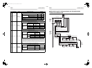
• Close the valves fully at the gas side, liquid side and balance pipe side. As there is a possibility that the nitrogen
gas will enter into the cycle of outdoor units, re-tighten the valve rods at the liquid side and balance pipe side
before applying pressure.
(When using MAP140 or MAP160, you do not have to re-tighten the liquid side valve rod as their valves at the
liquid side are ball valves.)
• For each refrigerant line, apply pressure gradually in steps at the liquid side, gas side and balance pipe side.
Be sure to apply pressure at the gas side, liquid side, and balance pipe side.
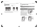
WARNING
Never use oxygen, flammable gases, or noxious gases in an airtight test.
Able to detect a serious leakage
1. Apply pressure 0.3MPa (3.0kg/cm²G) for 5 minutes or more.
2. Apply pressure 1.5MPa (15kg/cm²G) for 5 minutes or more.
Available to detect slow leakage
3. Apply pressure 3.73MPa (38kg/cm²G) for approx. 24 hours.
• If there is no pressure decrease after 24 hours, the test is passed.
V
L
V
H
Connected to indoor unit
Main piping
Gas side valve fully closed
Low pressure
gauge
High pressure
gauge
Brazed
Header outdoor unit
Fully
closed
Fully
closed
Connected to other follower units
Balanced pipe side valve
fully closed
Liquid valve fully closed
Service port
Service port
Copper pipe
Copper
pipe
Nitrogen
gas
Reducing
valve
Gauge
manifold
To gauge manifold
Liquid-side service port
Gas-side valve
Balance
service port
Balance valve
Piping at site
Piping at site
Piping at site
To outdoor unit
To
outdoor
unit
Liquid-side valve
Packed valve details
To
outdoor
unit
Gas-side
service port
Service port
27-EN 28-EN
+00EH99871699_01EN.book Page 14 Thursday, August 26, 2010 4:41 PM