


SMMS-i
Installation Manual
EN
SMMS-i
Installation Manual
–28–
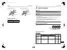
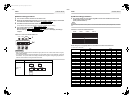
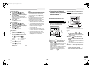
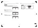
3 Push the button.
• The address of one of the indoor units
connected to the selected refrigerant line is
indicated on the LCD display and the fan and
louvers of the unit are activated.
At first, the current indoor unit address is
displayed in
SET DATA.
(No system address is indicated.)
4 Push the TIME / buttons repeatedly to
change the value of the indoor unit address
in SET DATA.
Change the value in SET DATA to that of a
new address.
5 Push the button to confirm the new
address on SET DATA.
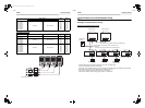
6 Push the button (left side of the
button) repeatedly to select another address
to change. Each time you push the button,
the indoor unit numbers in a refrigerant line
are indicated one after another. Only the fan
and louvers of the selected indoor unit are
activated.
Repeat steps 4 to 6 to change the indoor unit
addresses so as to make each of them unique.
7 Push the button.
(All the segments on the LCD display light up.)
8 Push the button to finish the procedure.
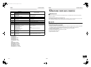
Resetting the address
(Resetting to the factory
default (address undecided))
Method 1
Clearing each address separately using a wired remote
controller.
Set the system address, indoor unit address and group
address to “0099” using a wired remote controller.
(For the setting procedure, refer to the address setting
procedures using the wired remote controller on the previous
pages.)
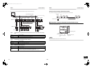
Method 2
Clearing all the indoor unit addresses on a refrigerate line at
once from the outdoor unit.
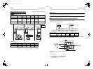
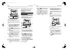
1 Turn off the refrigerant line to reset to the
factory default and set the header outdoor
unit of the line as below.
1) Disconnect the relay connectors between the
[U1, U2] and [U3, U4] terminals.
(Leave them as they are if they have already
been disconnected.)
2) Turn on dip switch 2 of SW30 on the interface
P.C. board of the header outdoor unit if the
switch is OFF.
(Leave it as it is if it has already been set to
ON.)
SET
4
8
5, 7
6
ON / OFF
TEMP.
TIME
SET CL
FILTER
RESET
TEST
TIMER SET
CODE No.
UNIT No.
SETTING
DATA
SET
R.C. No.
Press to finish
setting.
Finish
SET
SET
TEST
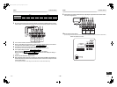
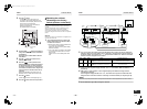
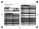
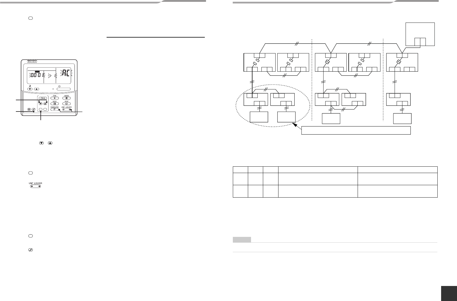
2 Turn on the indoor and outdoor units of the refrigerant line for which you want to initialize the
addresses. About one minute after turning on the power, confirm that the 7-segment display on
the header outdoor unit indicates “U.1. - - -” and operate the interface P.C. board on the header
outdoor unit of the refrigerant line as follows.
3 Confirm that the 7-segment display indicates “A.d. c.L.” and set SW01, SW02 and SW03 to 1, 1, 1
respectively.
4 After a time “U.1.L08” appears on the 7-segment display if the address clearing has been
completed successfully.
If the 7-segment display indicates “A.d. n.G.”, the outdoor unit may still connected with other
refrigerant lines. Check the connection of the relay connectors between [U1, U2] and [U3, U4].
NOTE
Take care to carry out the procedure above correctly; otherwise, addresses in other refrigerate lines may also be cleared.
5 Set the addresses again after finishing the clearance.
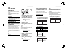
SW01 SW02 SW03 SW04 Clearable addresses
212
Confirm that the 7-segment display indicates
“A.d.buS” and turn SW04 ON for more than five
seconds.
System/indoor unit/group address
222
Confirm that the 7-segment display indicates
“A.d.nEt” and turn SW04 ON for more than five
seconds.
Central control address
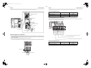
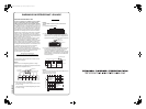
U3 U4
U1 U2 U5 U6
U1 U2
A B
U3 U4
U1 U2 U5 U6
U1 U2
A B
U3 U4
U1 U2 U5 U6
U1 U2
A B
U3 U4
U1 U2 U5 U6
U1 U2
A B
U3 U4
U1 U2
U1
U3
U2
U4
U5 U6
U1 U2
A B
Central control
controller
Header
unit
Follower unit
Follower unit
Remote
controller
Remote
controller
Remote
controller
Remote
controller
Indoor units to have their addresses initialized
Header
unit
Header
unit
55-EN 56-EN
+00EH99871699_01EN.book Page 28 Thursday, August 26, 2010 4:41 PM