


–19–
SMMS-i
Installation Manual
SMMS-i
Installation Manual
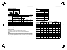
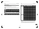
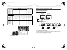
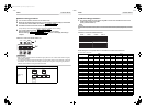
High efficiency model
MMY-AP3414*
MMY-AP3614*
MMY-AP3814*
MMY-AP4014*
MMY-AP4214*
MMY-AP4414*
MMY-AP4614*
MMY-AP4814*
3N~ 50Hz 380-400-415V
82.5
85.5
90.5
93.5
98.2
101.5
106.2
109.5
100
100
100
125
125
125
125
125
Model Phase and frequency Nominal Voltage
MCA
(A)
MOCP
(A)
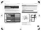
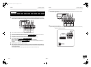
MMY-AP1624* 3N~ 50Hz 380-400-415V 46.9 63
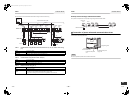
MMY-AP2424*
MMY-AP2624*
MMY-AP2824*
MMY-AP3024*
3N~ 50Hz 380-400-415V
70.4
72.4
74.5
76.5
80
80
100
100
MMY-AP3224*
MMY-AP3424*
MMY-AP3624*
MMY-AP3824*
MMY-AP4024*
MMY-AP4224*
MMY-AP4424*
MMY-AP4624*
MMY-AP4824*
3N~ 50Hz 380-400-415V
93.8
95.9
97.9
100.0
102.0
105.0
108.0
111.0
114.0
125
125
125
125
125
125
125
125
125
Model
Power Supply
MCA
(A)
MOCP
(A)
Phase and frequency Nominal Voltage
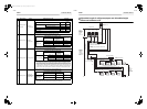
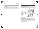
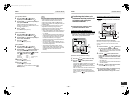
L1L2L3 N
L1L2L3 N L1L2L3 N L1L2L3 N
Circuit breaker
(Earth leakage breaker)
Main switch
(Fuse)
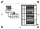
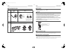
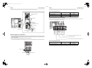
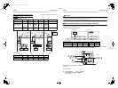
Specifications for communication wiring
◆Design of communication wiring
Summary of communication wiring
• Communication wiring and central control wiring use 2-core non-polarity wires.
Use 2-core shield wires to prevent noise trouble.
In this case, for the system grounding, close (connect) the end of shield wires, and isolate the end of terminal.
Perform the ground of wires at one side only for the header outdoor unit.
• Use 2-core non-polarity wire for remote controller. (A, B terminals)
Use 2-core non-polarity wire for wiring of group control. (A, B terminals)
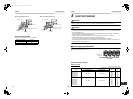
U1 U2 U3 U4 U5 U6 U1U2 U3 U4 U5 U6
U1 U2
U3 U4
U1 U2
AB AB U2U1U2U1 A B U2U1 A B
AB AB AB
Central control
controller
Header outdoor
Follower outdoor
Communication wiring between outdoor units (Shield wire)
Communication wiring between indoor and outdoor units
(Shield wire)
Communication wiring between indoor units (Shield wire)
Indoor unit
Indoor unit
Indoor unit
Indoor unit
Remote controller
Remote controller
Remote controller
(Group control)
37-EN 38-EN
+00EH99871699_01EN.book Page 19 Thursday, August 26, 2010 4:41 PM