


SMMS-i
Installation Manual
EN
SMMS-i
Installation Manual
–26–
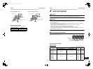
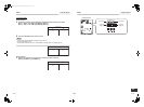
<Line (system) address>
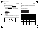
2 Push the TEMP. / buttons
repeatedly to set the CODE No. to .
3 Push the TIME / buttons repeatedly to
set a system address.
(Match the address with the address on the
interface P.C. board of the header outdoor unit in
the same refrigerant line.)
4 Push button.
(It is OK if the display turns on.)
<Indoor unit address>
5 Push the TEMP. / buttons
repeatedly to set the CODE No. to .
6 Push the TIME / buttons repeatedly to
set an indoor unit address.
7 Push the button.
(It is OK if the display turns on.)
<Group address>
8 Push the TEMP. / buttons
repeatedly to set the CODE No. to .
9 Push the TIME / buttons repeatedly to
set a group address. If the indoor unit is
individual, set the address to ; header
unit, ; follower unit, .
10
Push the button.
(It is OK if the display turns on.)
11
Push the button.
The address setting is complete.
( flashes. You can control the unit after
has disappeared.)
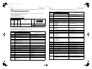
NOTE
1. Do not use address numbers 29 or 30 when setting
system addresses using the remote controller.
These 2 address numbers cannot be used on
outdoor units and the CODE No. [E04] (Indoor/
outdoor communication error) will appear if they are
mistakenly used.
2. If you set addresses to indoor units in 2 or more
refrigerate lines manually using the remote
controller and will control them centrally, set the
header outdoor unit of each line as below.
• Set a system address for the header outdoor unit
of each line with SW13 and 14 of their interface
P.C. boards.
• Turn off dip switch 2 of SW30 on the interface P.C.
boards of all the header outdoor units connected
to the same central control, except the unit that
has the lowest address. (For unifying the
termination of the wiring for the central control of
indoor and outdoor units)
• Connect the relay connectors between the [U1,
U2] and [U3, U4] terminals on the header outdoor
unit of each refrigerate line.
• After finishing all the settings above, set the
address of the central control devices. (For the
setting of the central control address, refer to the
installation manuals of the central control
devices.)
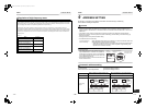
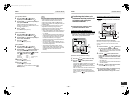
Individual : 0000
Header unit : 0001
In case of group
control
Follower unit : 0002
SET
SET
}
}
SET
TEST
SETTING SETTING
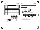
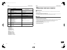
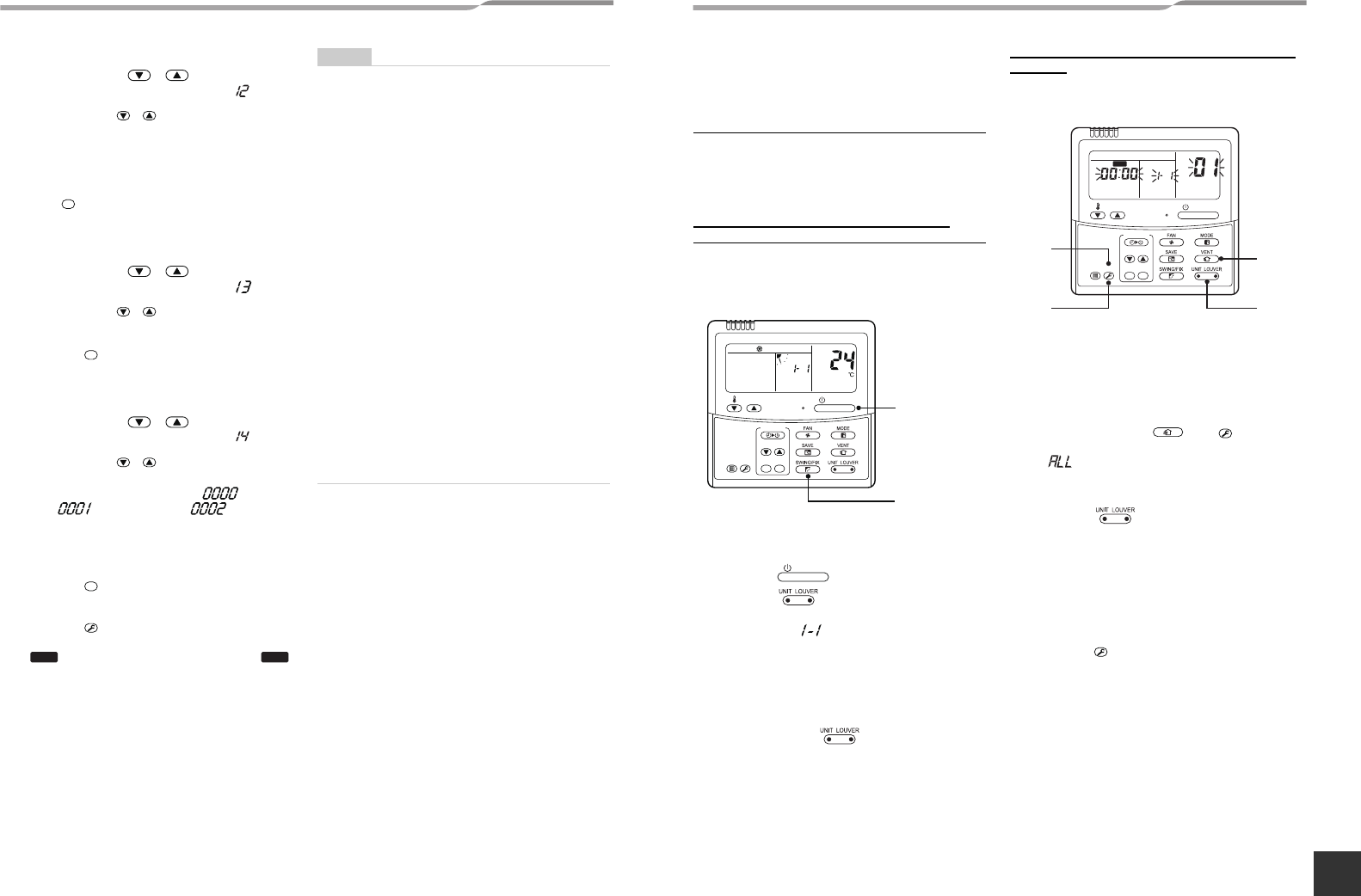
Confirming the indoor unit
addresses and the position of
an indoor unit using the
remote controller
◆Confirming the numbers and
positions of indoor units
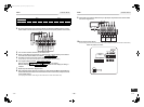
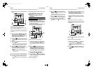
To see the indoor unit address of an
indoor unit which you know the position of
▼When the unit is individual (the indoor unit is
paired with a wired remote controller one-to-
one), or it is a group-controlled one.
(Execute it while the units are running.)
1 Push the button if the units stop.
2 Push the button (left side of the
button).
A unit numbers is indicated on the LCD (it will
disappear after a few seconds). The indicated
number shows the system address and indoor unit
address of the unit.
When 2 or more indoor units are connected to the
remote controller (group-controlled units), a
number of other connected units appears each
time you push the button (left side of the
button).
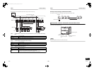
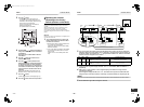
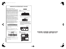
To find an indoor unit’s position from its
address
▼When checking unit numbers controlled as a
group
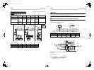
(Execute it while the units are stopped.)
The indoor unit numbers in a group are indicated one after
another. The fan and louvers of the indicated units are
activated.
1 Push and hold the and buttons at
the same time for more than 4 seconds.
• appears on UNIT No. on the LCD display.
• The fans and louvers of all the indoor units in the
group are activated.
2 Push the button (left side of the
button). Each time you push the button, the
indoor unit numbers are indicated one after
another.
• The first-indicated unit number is the address of
the header unit.
• Only the fan and louvers of the indicated indoor
unit are activated.
3 Push the button to finish the procedure.
All the indoor units in the group stop.
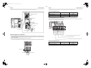
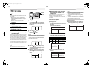
▼To check all the indoor unit addresses using
an arbitrary wired remote controller.
(When communication wirings of 2 or more
1
2
ON / OFF
TEMP.
TIME
SET CL
FILTER
RESET
TEST
TIMER SET
CODE No.
UNIT No.
Starts
running
ON / OFF
3
1
2
1
ON / OFF
TEMP.
TIME
SET CL
FILTER
RESET
TEST
TIMER SET
CODE No.
UNIT No.
SETTING
DATA
SET
R.C. No.
Stop
VENT
TEST
TEST
51-EN 52-EN
+00EH99871699_01EN.book Page 26 Thursday, August 26, 2010 4:41 PM