


All installations and services must be performed by qualified service personnel.
Likewise, the pressure drops for the two remaining segments in this branch can
be calculated in the same manner. They are,
....00702.0
...0129.0
GWinP
andGWinP
H
F
=Δ
=Δ
Referring to section (f) and (g) of the method, it is now necessary to resize each
of these duct segments for the actual required flowrate while maintaining the
pressure drops calculated above.
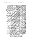
For instance, to maintain the pressure drop through segment “B” at the design
flowrate of 120 CFM + 115 CFM = 235 CFM, the required duct diameter is,
.9.04.9
00644.0
235*11*00123174.0
2058.0
82.1
ininD
B
≅=
⎥
⎦
⎤
⎢
⎣
⎡
=
For segment “C”, the design flowrate is 235 CFM + 115 CFM = 350 CFM, while
the pressure drop is 0.0257 in. W.G., then required duct diameter is,
.11.1.11
00257.0
350*6*00123174.0
2058.0
82.1
ininD
C
≅=
⎥
⎦
⎤
⎢
⎣
⎡
=
Including an 11 in., 90 degree elbow in segment “C”, the required diameter would
be,
()
.,11.4.11
00257.0
350*6.596*00123174.0
2058.0
82.1
ininD
C
≅=
⎥
⎦
⎤
⎢
⎣
⎡
+
=
or approximately the same as without the elbow.
For the segments “F” and “H” at 742 CFM and 798 CFM, respectively, the
required duct diameters are,
..14.3.14
.14.9.13
ininD
andininD
H
F
≅=
≅
=
Next, the branch of the system, which includes segments “D” and “E” can be
evaluated. To balance the system, the pressure drop for segments “D” and “E”
combined must be approximately equal to the pressure drops of segments “A”,
“B” and “C” combined. Thus,
.
CBADE
PPPPP
Δ
+
Δ
+
Δ
=
Δ
+Δ
67