


All installations and services must be performed by qualified service personnel.
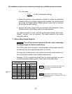
Typically, control wiring between the outdoor appliance and the indoor
thermostat, and if used, electronic air cleaner or humidifier, will be required. Field
wiring of control circuits should consist of copper conductors rated for at least
240 VAC with an insulation temperature rating conforming to Type T wire, 35°C
temperature rise. Depending upon code requirements, rigid or flexible conduit is
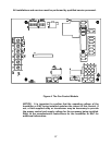
recommended, and may be required. Make connections between the thermostat,
and electronic air cleaner or humidifier (if used), and the fan control module,
inside the burner compartment. Consult the wiring diagram for the appropriate
connection points on the thermostat and the fan control module.
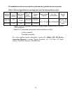
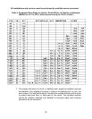
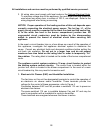
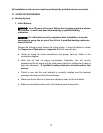
Table 5: Typical Electrical Requirements for Various OPB Models
Model
Potential/Frequency
/No. of Phases
(V/Hz/Ph)
Compressor
Running
Load
Current
(Amps) @
200 VAC
Compressor
Locked
Rotor
Current
(Amps) @
200 VAC
Condenser
Fan Full
Load
Current
(Amps) @
200 VAC
Supply/Retur
n Air Blower
Full Load
Current
(Amps) @
115 VAC
Oil
Burner
Assembly
Full Load
Current
(Amps)
@ 115
VAC
Maximum
Time Delay
Type Fuse
or Inverse
Time Circuit
Breaker
Size (Amps)
Recommend
ed Time
Delay Type
Fuse or
Inverse Time
Circuit
Breaker Size
(Amps)
Minimum
Recommended
75 deg. C.
Copper Power
Wiring Size
(AWG)
OPB24 15 58.3 40 30 10
OPB30 14.3 64 40 30 10
OPB36 18.6 79 50 35 8
OPB42
18 4
95
50
35
8
9.6 5.8208-240/60/1 0.8
Wire size selections in Table 5 are based upon Table 310-16 of the National
Electrical Code for three copper conductors, with insulation rated for 75 degrees
Celsius, contained in raceway at 30 degrees Celsius. For other wire insulation
temperature ratings and ambient conditions, refer to the National Electrical Code
for the minimum wire sizing requirements.
NOTICE: Before the unit is started, the installer and/or electrician must
check the following items.
1. Check every electrical connection of “push-on” or “screw-on” type terminals to
ensure that all wires and wire connectors are firmly secured. A loose terminal
can cause poor flow of electrical power to motors and to the refrigeration
compressor. This may result in very high current draws by these components.
If great enough, high current draw will cause blown fuses, burned wires and
contactor points, and pre-mature motor or compressor failure. Each electrical
connection has been factory checked, however, connections may loosen, due
to vibration, while the appliance is in transit. Please be certain that all
electrical connections remain tight.
2. Review wiring diagram for proper routing and connection of all field wiring.
25