


All installations and services must be performed by qualified service personnel.
h. The resistance of the take-off and the outlet register (or return grill)
should then be summed together to determine the total pressure drop for
each branch. This value should be close to the assumed value for the
pressure drop of the system. If it is not close, then flowrates for each
branch must be adjusted, or the design of the duct system must be
altered, to give the proper pressure drops. Usually, the cross-sectional
area of the ductwork should be changed in order to adjust the pressure
drop to a suitable value.
Refer to Example 2, in Appendix B: Calculations of this manual, for a
sample calculation of how to use this method for sizing the supply side
ductwork for a residence.
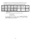
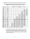
Table 3 shows the air handling capacities of 100-ft. lengths of circular and
rectangular ductwork based on a 0.1 in. W.G. static pressure drop. The first
column to the right is the air flowrate and the second is the required diameter
for a circular duct. The third column is the required cross-sectional area of the
duct and the other columns to the left are rectangular ducts with sufficient
cross-sectional area to handle the flow at the specified pressure drop. [For
lengths of ductwork less than 100 ft., simply multiply 0.1 in. W.G. by the ratio
of the actual duct length (in feet) over 100 ft. for the approximate pressure
drop.] Use the supplier’s catalog for proper sizing of outlet air registers and
return air grills to insure that they provide the required flowrate at the desired
pressure drop.
21