


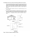


All installations and services must be performed by qualified service personnel.
6. The following method can be used to size ductwork when air velocities are
low to moderate.
a. Using a floor view of the residence, determine, or layout, the locations of
the supply registers and the return air grills. (Generally, supply registers
should be located close to sources of heat loss, i.e. windows and doors,
around the perimeter of the building. Return grills should be located in
central positions as far away from the supply registers as practical.)
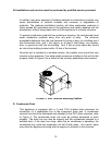
b. Find a location for the appliance outside the building that minimizes the
amount of ducting required to connect the appliance to the supply and
return air duct systems. Consider issues of access to the oil supply and
electrical service, required service and venting clearances, exposure to
sunlight, and operating noise when selecting this location.
c. Plan an efficient layout for the ductwork connecting each of the supply
air registers in the supply system to the unit. Plan and layout ductwork
connecting each of the return air grills in the return system to the unit.
Measure or estimate the length of duct between each register and grill.
d. Select values for the airflow through each register and grill.
e. Select values for the pressure drops of both the supply and return air
systems. Each branch of the supply (or the return) air system will have
this pressure drop. The total pressure drop of the supply and return air
systems added together cannot exceed the maximum external static
pressure that can be supplied by the appliance blower.
f. Determine the required flowrate for each branch of the supply and return
air systems. The total air flowrate, by adding the air flowrate of each
branch of the supply system, must equal the minimum required air
flowrate (refer to part 3, above). Likewise, the air flowrate of each of the
branches of the return air system must sum to the required minimum
flowrate.
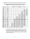
g. Using the selected air flowrates for each component of the duct system
and manufacturer’s literature, or published literature on duct system
pressure drops, the pressure drop for each component in the duct
system can be estimated.
(Chapter 32 of the ASHRAE Handbook – Fundamentals
is an excellent
source of duct system design principles and pressure drop data.)
Conversely, for a specified type of fitting, it is also possible to determine
the required size or diameter of the component for a specified pressure
drop and flowrate.
20