


All installations and services must be performed by qualified service personnel.
5. A readily accessible, design-certified, manual oil shutoff valve, with a non-
displaceable rotor member, shall be installed in the fuel oil supply piping
within 6 feet of the appliance.
6. A pipe union, or flanged connection, shall be provided downstream from
the manual oil shutoff valve to permit removal of the appliance oil pump.
Pipe unions must be the ground joint type or flanged-jointed using a
gasket resistant to the corrosive action of fuel oils.
7. Pipe dope or thread sealant design-certified to be resistant to the action of
fuel oils should be used on all threaded joints. Thread sealant should only
be applied to the male member of a joint. The first two threads on the end
of the male member of each pipe joint should be clean and free from
thread sealant.
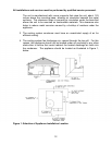
8. Connection of the oil supply piping to the appliance should be made from
the left-hand side of the burner, facing the burner compartment cover.
9. When tubing is to be used for fuel oil supply lines, use of continuous runs
of heavy wall copper tubing is recommended. Avoid running tubing
against any type of heating unit and across ceiling or floor joists. If
possible, install the tubing under the floor.
10. Where tubing is used for fuel oil supply lines, insure the tubing contains no
kinks, sharp bends, or collapsed regions where the inside cross-sectional
area of the tube is greatly reduced. These will excessively reduce the flow
of oil.
11. Flared fittings should be used at all tube joints, when tubing is used for
fuel supply lines. Do not use compression fittings. Avoid the use of
tube fittings in inaccessible locations.
Burners are equipped with a single-stage, fuel pump. This type of fuel pump,
when connected with a supply line only, is satisfactory where the fuel supply is
level with, or above the burner thus permitting gravity flow of oil to the burner. If
the tank is above the burner, and gravity oil feed to the burner is permitted, a
single line system may be used. The line should have a gradual slope downward
of approximately 1/2 inch per foot, or more, from the tank to a point directly below
where it is connected to the pump. Pitching the line upward toward the tank will
help prevent the formation of air pockets in the line.
NOTICE: An oil safety valve or a delayed-action, solenoid valve should be
installed in the oil supply line of all gravity-fed systems.
16