


vi 05206H DCN5910
Figure 3-6. Analog Output Manual Calibration............................................................................ 33
Figure 3-7. Analog Output Recorder Offset Calibration .............................................................. 34
Figure 4-1. Catalytic Cartridge ..................................................................................................... 36
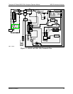
Figure 4-2. Thermocouple Location ............................................................................................. 37
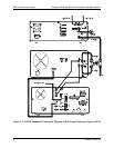
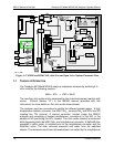
Figure 5-1. M201E Functional Block Diagram
............................................................................ 42
LIST OF TABLES
Table 1-1. M201E Operating Specifications ................................................................................ 14
Table 2-1. Zero Calibration Procedure – Zero Gas Through the SAMPLE Port ......................... 16
Table 2-2. Zero Calibration Procedure - Zero Gas Through ZERO Port ..................................... 17
Table 2-3. NO Calibration Procedure – NO Gas Through the SAMPLE Port............................. 18
Table 2-4. NO Calibration Procedure - NO Gas through the SPAN Port.................................... 19
Table 2-5. Confirming Ammonia Converter Efficiency ............................................................... 21
Table 2-6. NH3 Calibration Procedure – NH3 Gas Through The SAMPLE Port........................ 22
Table 2-7. NH3 Calibration Procedure – NH3 Gas through the SPAN Port................................ 23
Table 3-1. Analog Output Data Default Settings.......................................................................... 25
Table 3-2. Analog Output Pin-Outs.............................................................................................. 26
Table 3-3. Analog Output Voltage Range Min/Max .................................................................... 27
Table 3-4. Analog Output Current Loop Min/Max ...................................................................... 27
Table 3-5. ZERO/SPAN Analog Output Signal Calibration Tolerances...................................... 32
Table 4-1. Preventative Maintenance Schedule............................................................................ 35
Table 4-2. M501 NH
3
, Converter Rebuild Parts List.................................................................... 36
Table 4-3. Analyzer Flow Check.................................................................................................. 39