


05206H DCN5910 25
3.0 CONFIGURABLE ANALOG OUTPUT OVERVIEW
There are three different methods to extract concentration data from the E-Series
analyzers. By one method, the operator can set up an iDas (internal data
acquisition) configuration either through the user display or using TAPI’s windows
based software called APICOM. The analyzer stores data internally, which is
available later for download through the RS-232 or Ethernet port. The second
method involves the use of hyperlink where the user sends text based commands,
to retrieve data, through the RS-232 port. With the third method, the operator can
interface a strip chart recorder and/or data-logger to the analyzer analog outputs.
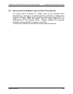
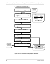
The following sections outline the steps necessary to calibrate and configure the
analog outputs.
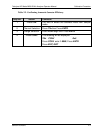
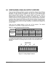
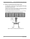
There are four analog outputs on the rear of the analyzer. The default
configurations of the M201E analog outputs are as follows:
Table 3-1. Analog Output Data Default Settings
CHANNEL DEFAULT SETTING
ANALYZER
A1 A2 A3 A4
TNxCNC1
NH
3
CNC1 NOCNC1
NO
2
CNC1
5 Volts 5 Volts 5 Volts 5 Volts
M201E
500 PPB 500 PPB 500 PPB 500 PPB
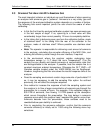
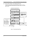
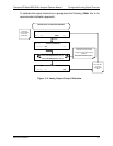
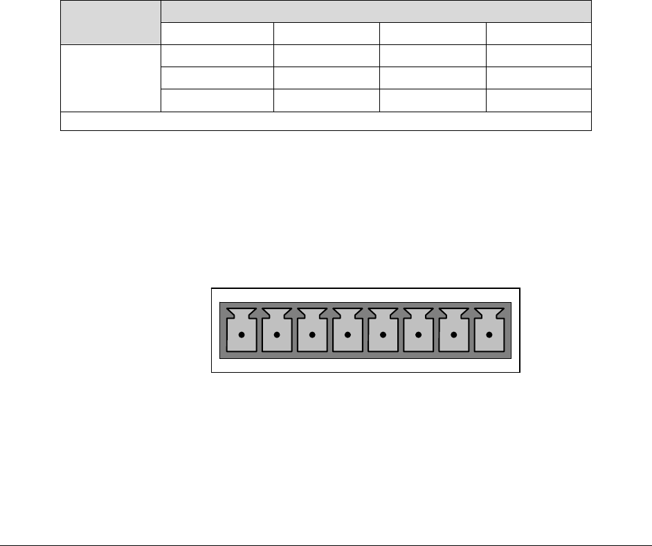
To access these signals attach a strip chart recorder and/or data-logger to the
appropriate contacts of the analog output connecter on the rear panel of the
analyzer.
ANALOG OUT
A1
A
2
A
3
A
4
+ - + - + - + -
Figure 3-1. Analog Output Connector