


Configurable Analog Output Overview Teledyne API Model M201E NH
3
Analyzer Operator Manual
32 05206H DCN5910
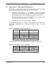
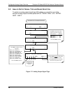
3.4 MANUALLY CALIBRATING ANALOG OUTPUT SIGNAL LEVELS
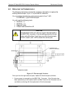
The analog outputs in voltage mode can be manually calibrated to closely match
the characteristics of the data recorder. Outputs configured for 0.1V full scale
should always be calibrated manually.
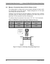
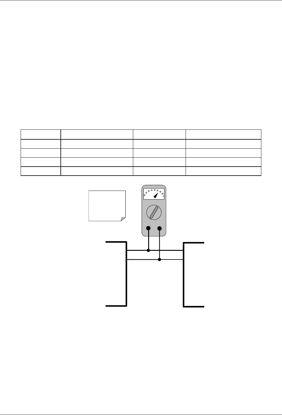
Calibration is done through the instrument software in conjunction with a voltmeter
connected across the output terminals. Adjustments are made using the front
panel keys. First the zero-point is set then the span-point.
The software allows this adjustment to be made in 100, 10 or 1 count increments.
Table 3-5. ZERO/SPAN Analog Output Signal Calibration Tolerances
Full Scale Adjust Zero Within Span Voltage Adjust Span Within
0.1 VDC ±0.0005V 90 mV ±0.001V
1 VDC ±0.001V 900 mV ±0.001V
5 VDC ±0.002V 4500 mV ±0.003V
10 VDC ±0.004V 4500 mV ±0.006V
VDC
+DC Grnd
V OUT +
V OUT -
V IN +
V IN -
Recording
Device
ANALYZE
R
See Table 6-8 for pin
assignments on the
for ANALOG
connector located on
the instruments rear
panel
Figure 3-5. Setup For Calibrating Analog Output Signal Levels