


Page 6
2. Locate the vent terminal so the vent exhaust does
not settle on building surfaces and other nearby
objects. Vent products may corrode such surfaces
or objects.
3. Locate the vent terminal at a sufficient horizontal
distance from any gas or electric metering,
regulating or relief equipment. In the United
States, this distance must be at least 4 feet
(1.21 m). In Canada, it must be at least 10 feet
(3.04 m).
4. Locate the vent terminal at a sufficient horizontal
distance from any building opening. Take special
care to assure that combustion products do not
enter a building through windows, doors,
ventilation inlets, etc. In the United States, this
distance must be at least 4 feet (1.21 m). In
Canada, it must be at least 10 feet (3.04 m).
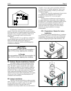
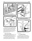
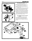
As shown in Figures 8 and 9, the combustion air
intake and the vent outlet must be installed no closer
together than 18" (45.7cm) and no farther apart than
60" (1.5m). The combustion air inlet opening must
face downward to prevent entry of rain or snow. The
vent outlet must discharge away from the combustion
air inlet - normally in a horizontal direction when on a
wall and vertically upward when on a roof. Both
should terminate at least 12" (30.5cm) above the snow
accumulation level. In locations with freezing climate,
extension of the vent pipe outside of the building
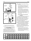
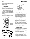
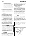
should be minimized. The insect screens provided with
the heater must be installed at the combustion air and
vent pipe openings as shown in Figure 10. Insect
screens are sized to fit the inside of a 5" PVC pipe
fitting. Trim them as necessary for smaller pipe sizes.
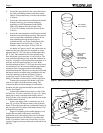
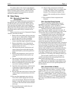
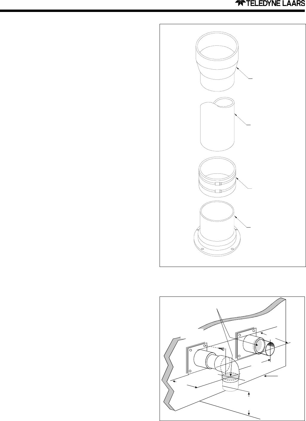
Connect the vent pipe to the heater vent collar
with an air-tight corrosion-resistant clamp. The
connection must not allow leakage of combustion
products into the space but should be removable for
service. See Figure 7.
Connect the combustion air pipe to collar of the
air filter box. For this combustion air pipe only, sheet
metal pipe is most convenient and can be screwed
directly to the collar. Seal the joint with silicone sealer
or similar mastic material.
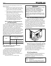
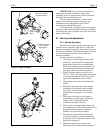
Install vent piping with a continuous rise of at
least 1/4" per foot (20 mm per meter) away from the
heater. This will assure that any condensate forming in
the vent pipe will flow back to the heater where it can
be disposed of properly.
Support vent piping with suitable hangers so its
weight does not bear on the heater or building
penetration and so that piping joints are not strained.
Support horizontal runs at intervals no greater than
6 feet (1.82 meters), and closer if necessary to avoid
sagging. Sagging can trap condensate water and block
the vent.
Figure 8. Vent and Combustion Air Terminals at
Exterior Wall.
Figure 7. Indoor Vent Connection, Hi-E2 Pool Heater
PVC Adapter
when required
4" PVC Pipe
Field-provided
Clamping
Connector
with Neoprene,
Nitrile or EPDM
Sleeve
Hi-E2 Vent Collar
7" min.
12" min.
to maximum
snow level
Grade level
or normal
snow
18" min.
60" max
6" min.
Combustion
Air Pipe
Vent Exhaust
Pipe
Special Insect Screens Installed
(See Fig. 10)