


Hi-E2
Page 11
To connect a three-wire remote control harness
(not supplied with the heater), order an E0120000 wire
harness assembly which connects to the Flex-Temp
control panel. Installation instructions are included
with the wire harness assembly.
2K. Water Piping
2K-1. Reversal of Heater Water
Connections
The Hi-E
2 is shipped with water connections on
the right side, but it can be modified in the field to
provide left-side water connections. This is done by
removing the water headers and re-installing them
opposite to their original location. Some of the heater
wiring and control components must be relocated, so
this change must be done only by a trained service
technician.
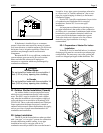
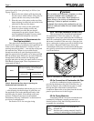
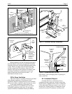
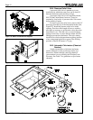
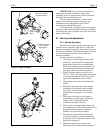
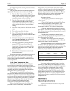
Water connection reversal is illustrated in Figures
18 and 19. Proceed as follows:
1. Remove the vent exhaust grille by removing
the four screws which retain it. Retain these
and all other parts for later reassembly.
2. Remove the top cover by removing the
screws around the edges, under the overhang.
3. Remove the header covers. Note that the
return header cover is retained by wing nut
fasteners inside the heater.
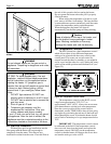
4. Disconnect the pressure switch wires and
remove the pressure switch tube from the
inlet/outlet header by unscrewing the brass
fitting.
5. Remove the temperature control sensor by
removing the retainer bracket and its cap
screws.
6. Disconnect the limit switch wires from the
limit switches. The limit switches and the
short wire between them may be left in place.
7. Remove both headers by unscrewing eight
cap screws retaining each header.
8. Install the inlet/outlet header on the left side
of the heater and the return header on the
right. Position gaskets carefully to avoid
water leaks.
9. Re-route the limit switch wires in front of the
venturi tailpipe and attach them to the limit
switches.
10. Re-route the temperature sensor wires in
front of the venturi tailpipe and insert the
sensor into the header. When the inlet/outlet
header is on the left side, the sensor opening
is at the rear. Re-install the retainer bracket
and screw.
11. Re-install the pressure switch tube and
fitting. Relocate fitting.
12. Adjust wiring and pressure switch tube
routing so that they don't rest on sharp edges
or on the hot surfaces of the combustion
chamber. The combustion chamber is the
portion of the assembly just above the heat
headers.
13. Re-assemble all other components and
fasteners.
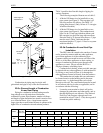
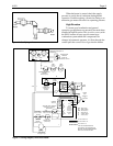
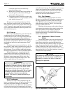
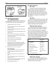
2K-2. Pool/Spa Piping Systems
Figure 20 illustrates typical piping for pool
equipment in pool/spa combination pools. With its
Flex-Temp temperature control, the Hi-E
2 is
particularly suitable for this type of pool installation.
The heater must be protected from back-
siphoning of water, which can result in dry starts. If
there is any chance of back-siphoning, provide a check
valve between the pool and the filter pump inlet.
Arrangement of pool system components other
than as illustrated in these diagrams can affect the
operation of the heater’s water pressure switch.
Location of the heater above or below the pool water
surface can also affect operation of the switch. In
general, the pressure switch can be adjusted to
accommodate this effect if the heater water connections
are no more than six feet below the pool water surface
and no more than 15 feet above it. See instructions for
pressure switch adjustment in the heater start-up
section of this manual for more information about this.
Note that when pool equipment is located below the
pool surface a leak can result in large scale water loss
or flooding. Teledyne Laars cannot be responsible for
such water loss or flooding or the damage caused by it.
Do not install a shutoff valve or any kind of
variable restriction in the water piping between the
heater outlet and the pool/spa.
Pool systems with water flow rates higher than
125 GPM require an adjustable external bypass at the
heater. See the section on start-up and adjustment for
this information.
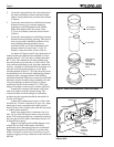
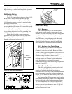
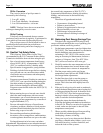
2K-3. Connections at Heater
The Hi-E
2 has a universal water header and
flange design. With this feature, a variety of piping
materials and sizes can be used at the heater. 1-1/2"
PVC or 2" copper pipe can be connected directly to
the heater using the rubber “donut” gaskets provided
with the heater. 2" PVC or metal pipe can be threaded
directly to the flanges and 1-1/2" schedule 40 metal
pipe can be used with the rubber donut gaskets (see
Figure 21).