


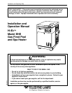

SECTION 1
General Information
1A Introduction ........................................................... 1
1B Description ............................................................ 1
1C Warranty................................................................ 1
SECTION 2
Installation Instructions
2A General Requirements .......................................... 1
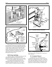
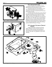
2B Heater Assembly and Preparation ........................ 2
2C Heater Location ..................................................... 2
2D Installation Clearances.......................................... 2
2E Outdoor Installation ............................................... 2
2F Outdoor Shelter Installation (Canada) .................. 3
2G Indoor Installation.................................................. 3
2G-1 Preparation of Heater For
Indoor Installation.................................................. 3
2G-2 Combustion Air Requirements for
One-Pipe Installation ............................................. 4
2G-3 Two-Pipe Installation (Direct Vent) ....................... 4
2G-3a Connection of Combustion Air Pipe ...................... 4
2G-3b Piping Materials..................................................... 4
2G-3c Size and Length of Combustion
Air and Vent Piping ............................................... 5
2G-3d Combustion Air and Vent Pipe Installation ........... 5
2G-3e Room Ventilation ................................................... 7
2H Condensate Disposal ............................................ 7
2I Gas Supply and Piping ......................................... 8
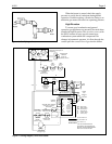
2J Electric Wiring ..................................................... 10
2J-1 Electrical Power................................................... 10
2J-2 Bonding ............................................................... 10
2J-3 Auxiliary Time Clock Wiring ................................ 10
2J-4 Remote Operation ............................................... 10
2K Water Piping........................................................ 11
2K-1 Reversal of Heater Water Connections .............. 11
2K-2 Pool/Spa Piping Systems.................................... 11
2K-3 Connections at Heater......................................... 11
2K-4 Pressure Relief Valve .......................................... 12
2K-5 Automatic Chlorinators (Chemical Feeders)....... 12
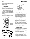
2L Start-Up and Adjustment..................................... 13
2L-1 Normal Operation................................................ 13
2L-2 Start-Up ............................................................... 14
2L-3 Condensate ......................................................... 14
2L-4 Gas Pressure....................................................... 14
2L-5 Adjustment of Water Pressure Switch............... 14
2L-6 Water Temperature Rise..................................... 15
SECTION 3
Operating Instructions
3A Start-Up Procedure ............................................. 16
3B Temperature Controls ......................................... 16
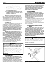
3C Lighting and Shutdown ....................................... 17
3C-1 Lighting the Heater.............................................. 17
3C-2 Shutdown............................................................. 17
3D Water Chemistry ................................................. 17
3D-1 Pools.................................................................... 17
3D-2 Spas .................................................................... 17
3D-2a Spa Water Chemistry.......................................... 17
3D-2b Water Changing .................................................. 17
3D-2c Corrosion ............................................................. 18
3D-2d Testing................................................................. 18
3E Spa/Hot Tub Safety Rules................................... 18
3F Swimming Pool Energy Saving Tips................... 18
3G Seasonal Care..................................................... 19
3G-1 Spring and Fall Operation ................................... 19
3G-2 Winterizing .......................................................... 19
3H Periodic Inspection.............................................. 19
3H-1 Owner Inspection ................................................ 19
3H-2 Professional Inspection....................................... 20
SECTION 4
Maintenance and Service
4A General ................................................................ 20
4B Induced-Draft Combustion System..................... 21
4C Heater Components and Their Operation........... 21
4D Combustion Air Filter .......................................... 22
4E Electrical Trouble Shooting ................................. 22
4E-1 115V Electrical Power Supply ............................. 22
4E-2 Control Circuit Trouble Shooting......................... 23
4E-2a Transformer......................................................... 23
4E-2b Fuse..................................................................... 23
4E-2c Fireman Switch and External Interlocks ............. 24
4E-2d Limit Switches ..................................................... 24
4E-2e Water Pressure Flow Switch............................... 24
4E-2f Temperature Control ........................................... 24
4E-2g Venturi Pressure Switch ...................................... 24
4E-2h Ignition Control .................................................... 24
4E-2i Burner Limit Switch ............................................. 25
4E-2j Vent Limit Switch ................................................ 25
4E-2k Combustion Blower ............................................. 25
4E-2l Igniter................................................................... 25
4F Venturi Combustion Flow System....................... 25
4F-1 Pressure Measurement Ports.............................. 25
4F-2 Venturi System Checkout.................................... 26
4F-2a Unfired Venturi Differential Pressure .................. 26
4F-2b Gas Pressure Offset............................................ 26
4F-2c Gas Orifice Differential........................................ 26
4F-3 Air Flow Investigation .......................................... 27
4F-3a Combustion Air Flow ........................................... 27
4F-3b Flow in Heater and Vent...................................... 28
4F-4 Fuel Gas Type and Gas Orifice Size .................. 28
4F-5 High Elevation Operation .................................... 28
4G Combustion Condensate..................................... 28
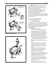
4H Major Component Service................................... 29
SECTION 5
Capacities and Dimensions
5A General Information ............................................ 29
SECTION 6
Replacement Parts
6A. General Information ............................................ 30
TABLE OF CONTENTS