


Page 20
SECTION 4.
Maintenance and Service
WARNING
SERVICING SAFETY
Some of the servicing procedures for the Hi-
E2 pool heater are hazardous because they
involve fuel gas, electricity, moving parts and
procedures which require testing or temporary
bypass of safety controls. For this reason, the
heater must be serviced only by a qualified
professional service technician.
IMPROPER SERVICE HAZARD
The Hi-E2 pool heater incorporates unique
design features. Incorrect service of this
heater can result in personal injury or damage
to property. To avoid such hazards, the heater
must be serviced only by a qualified
professional service technician.
4A. General
A qualified professional technician must service
the Hi-E
2 pool heater using Teledyne Laars service
procedures. Before calling for service, however, the
owner should check for obvious problems. The other
components in the pool system, including pump, filters
and strainers, water valves, gas supply, electrical
power and time clocks, have an effect on heater
operation.
Confirm that the Flex Temp heater control is set
to “pool” or “spa” and that the corresponding
temperature knob is set high enough to make the heater
operate. Make sure the pump is operating, that the
filter and strainers aren’t clogged, that there are no
mis-positioned water valves, that the gas or electric
power supplies aren’t shut off and that time clocks are
3H-2. Professional Inspection
Inspection by a qualified professional technician,
performed at least once a year by a qualified
professional technician, are required to keep the heater
operating efficiently through the years. The following
basic checks should be performed.
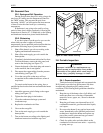
1. Inspect the condensate disposal system to be sure
that condensate flows freely.
2. Replace combustion air filter.
3. For heaters installed with combustion air or vent
piping, inspect screens at the inlet or outlet of
these pipes. Clean screens as necessary to assure
free flow (See illustrations in combustion air and
vent pipe installation section).
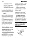
4. Make sure that the pressure switch operates
properly by shutting the filter pump off and on a
few times. The burner should go off immediately
after the pump stops. An ignition sequence
should start shortly after the pump is turned
back on.
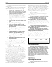
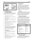
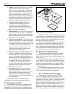
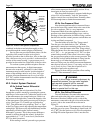
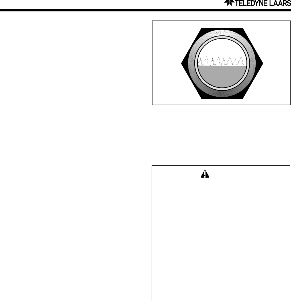
5. Make a visual check of the main burner flame.
The flame can be seen in a mirror/viewport
arrangement in the upper part of the heater. The
flame should be light blue and the burner surface
should be dark, with only a few glowing fibers
(see Figure 28).
6. Inspect the gas and electronic controls, including
the following:
a. High temperature limit switch
b. Water pressure switch
c. Venturi pressure switch
d. Automatic gas valve
e. Burner temperature limit switch
f. Vent limit switch
g. Temperature control
h. Control circuit fuse
7. Perform a temperature rise test in accordance
with Section 2L.
8. If the heater is equipped with a pressure relief
valve, clean any accumulated corrosion and make
sure that water runs freely through it.
9. Inspect the outside of the combustion chamber
and burner for corrosion and indication of
improper operation.
10. Regularly inspect electrical controls for
deterioration. Repair and replace as necessary.
NOTE: Keep this manual in a safe place for
future reference by you and your professional
technician when inspecting and servicing the heater.
Figure 28. Burner Flame (visible near top of heater in
mirror).