


Hi-E2
Page 13
IMPORTANT: If an automatic chlorinator is
being used, equip the chlorinator with an anti-
siphoning device so that chlorine will not siphon into
the heater after the pump shuts off.
Wire an electric chlorinator so that it cannot
operate unless the filter pump is running. If the
chlorinator has an independent clock control,
synchronize it with the filter clock.
If the chlorinator is equipped with its own pump,
install it so that it introduces the chlorine downstream
from the heater, and, if possible, below the level of the
heater outlet fitting.
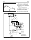
2L. Start-up and Adjustment
2L-1. Normal Operation
The Hi-E
2 pool heater operates automatically. It
provides heat in response to the selector switch and
temperature settings on the FlexTemp control panel on
the front of the heater. The heater has internal controls
to sense adequate water flow and to handle any
abnormal condition.
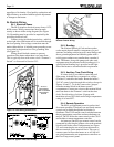
Normal operation is as follows:
1. The pool/spa system filter pump provides
water flow. A pressure-flow switch in the
heater detects water flow and enables the
FlexTemp control to operate the heater. (If
the recommended fireman switch has been
provided, it must also enable operation.)
2. If the FlexTemp selector switch is set to
"Pool" or "Spa", and if the water temperature
is not warm enough, the FlexTemp control
signals the combustion system to start.
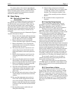
3. The ignition control starts the combustion
blower.
4. When the venturi pressure switch detects
combustion air flow and when a suitable
“pre-purge” time has been allowed, the
ignition control energizes a “hot surface”
igniter.
5. The igniter is allowed to reach ignition
temperature, at which it glows bright red-
orange. This is visible through the
combustion chamber view port.
6. The gas valve is opened and gas flows into
the combustion air. The gas/air mixture flows
through the burner into the combustion
chamber. It is ignited by the igniter.
7. The ignition control electronically senses
successful ignition by “flame rectification”,
and the gas valve is allowed to stay on. The
igniter is de-energized.
8. The heater operates for as long as the
FlexTemp control demands heat, subject to
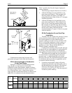
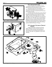
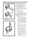
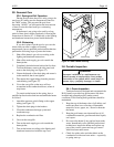
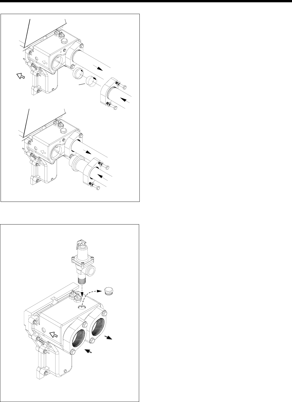
Method For Installing
Any Threaded Pipe
Figure 21. Piping to Heater.
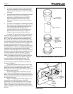
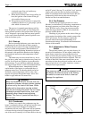
For Nonthreaded Pipe
or Tube, Discard
Plastic Sleeve
Use
Plastic
Sleeve
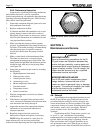
Figure 22. Pressure Relief Valve Installation.
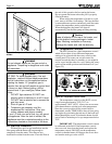
Water
In
Out