


Page 22
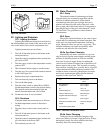
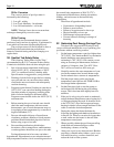
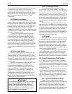
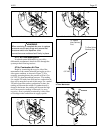
The filter should be replaced annually in normal
service. Heavy use of the heater or operation in adverse
environments may dictate more frequent replacement,
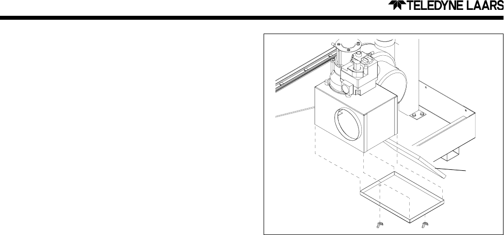
however. It can be removed through the bottom of the
filter box as illustrated in Figure 30.
Remove the wing nuts retaining the bottom panel
and remove the panel. Grasp the bottom edge of the
filter and pull it downward and to the right. Replace it
only with the specified part available from a Teledyne
Laars representative. Push the replacement filter into
the tracks at the front and rear of the filter box.
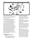
4E. Electrical Trouble Shooting
This section describes procedures for checking
the electrical power and control components of the
heater one at a time and in the order they appear in the
control circuit.
These procedures require a Volt-Ohm meter with
0-150 VAC VAC range, and 0-1000 Ohm resistance
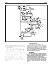
range. Figure 31 shows the power and control circuits,
and where to take measurements. Location numbers in
circles have been added, and will be referenced in the
following sections.
As stated at the beginning of this manual, some
of these procedures are hazardous. Only a qualified
service technician should service the heater.
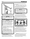
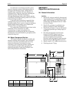
4E-1. 115V Electrical Power Supply
The electrical components of the Hi-E2 pool
heater are designed to operate with supply voltage
ranging from 103V to 126V at 60 Hz. Measure supply
voltage at the “hot” and “neutral” wirenut connections
in the heater electrical junction box (identified as
points A and B on the wiring diagram). If no voltage is
present, correct this external to the heater. Circuit
breakers, time clock settings or similar devices may be
the problem. Voltage outside of the above range may
be due to poor wiring, poor connections, other loads
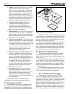
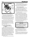
5. Igniter - The hot surface igniter is a ceramic
element which becomes very hot when
electrical power is applied to it. It functions
both as an igniter and as flame sensor. As a
sensor, it is the electrode through which the
ignition control detects “rectification” of
current passed through the flame. Inadequate
rectification indicates an unsatisfactory flame
condition. The ignition control responds to
the flame signal provided by the ignitor.
6. Venturi Pressure Switch - This switch
verifies that air is flowing through the
combustion system by sensing pressure
reduction at the venturi throat (relative to
pressure at the venturi inlet). It shuts off the
heater if air flow is inadequate.
7. Limit Switches - Two limit switches prevent
excessive water temperature - one within the
heat exchanger and one for water leaving the
heater. If either senses excessive temperature,
burner operation is interrupted.
8. Water Pressure Switch - This control senses
whether or not water is available to the heater
by measuring back pressure inside of the heat
exchanger. If the pool water pump fails or the
water filter is blocked, the pressure switch
prevents operation of the burner. It can be
affected by the installation conditions as
discussed earlier in this manual.
9. Burner Temperature Limit Switch - This is
a single-use switch which detects abnormal
burner temperature. It is a disc-type switch
which is held against the burner plenum by a
sheet metal bracket. It has the appearance of
an automatic-reset switch in that it has no
reset button. However, it will reset only if
cooled to -31
o
F, and therefore will not
recycle. The burner limit switch prevents or
interrupts burner operation if the burner
plenum becomes too hot.
10. Vent Limit Switch - The vent limit switch
protects the vent system from excessive
exhaust temperature. It is located on the vent
diffuser above the combustion blower. It
interrupts burner operation if temperature
becomes too hot for the plastic materials used
to vent the heater.
See the earlier section entitled Start-up and
Adjustment for the normal sequence of operation.
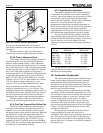
4D. Combustion Air Filter
The combustion air filter is a rectangular foam
filter located in a box near the bottom of the control
compartment.. The filter removes lint and large scale
dust particles to prevent blockage of the burner media.
Figure 30. Air Filter Replacement.
Filter