


Page 8
Before treatment, its “pH” is typically in the 3.5 to 6.0
range.
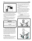
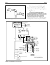
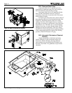
Handling and disposal of condensate is not
complicated, but it must be done correctly to prevent
problems or complaints. A trap/neutralizer assembly is
provided with the heater to simplify installation. This
assembly is easily installed in the base of the heater.
Figure 11 illustrates its installation and the routing of
drain tubes.
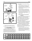
To install the condensate assembly, first install
the short length of 5/8" I.D. tubing on the barbed
fitting on the bottom of the condensate collector. Then
drop the condensate tray into the opening in the base
pan of the heater, bending the 5/8" tubing as necessary
to get the tube into the tray. Readjust the 5/8" tubing
so that its lower end is 1/4" - 3/8" above the bottom of
the tray. The tray can be positioned with the outlet
fitting to the right, as shown in Figure 11, or with the
fitting to the left, depending on the direction required
for condensate disposal. Connect the piece of 1/2" I.D.
tubing to this outlet fitting and route it out of the heater
through the hole in the side of the base panel. This tube
carries condensate to the drain. If this disposal tube is
routed to the left, remove the plug button from the hole
on the left side of the base panel and push it into the
hole on the right side.
Connect the remaining short piece of 3/8" I.D.
tubing to the barbed tee fitting in the tubing
immediately in front of the blower. Position this tubing
so that its bottom end is 1/4"-3/8" above the bottom of
the condensate tray. This tube provides drainage for
the vent duct and blower.
A package of limestone gravel neutralizer is
provided with the condensate assembly. Place this
gravel in the tray after installing and properly
positioning all tubes. Be sure that a limestone pebble
does not plug any of the tubes. Place the cover on the
tray when this is done.
It is important that there be no sagging sections
of tubing to trap water. Drainage to the trap and out of
the trap to the drain must be assured by continuous
downward routing of these tubes. It may be necessary
to elevate the heater to provide downward routing. The
outlet of the disposal tube must be open to the air.
If a gravity drain is not available, a condensate
pump must be provided in the field. Suitable
condensate pumps are available commercially at air
conditioning equipment distributors.
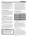
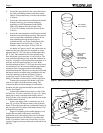
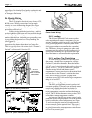
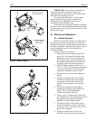
Incorrect installation of the condensate assembly
or tubing can result in overflow or waterlogging of the
vent. In normal operation, water accumulates in the
tray at the level of the outlet fitting, and this provides a
“water seal” which accommodates combustion system
pressures. Figure 12 illustrates the water seal. Note
that water is “pulled” up toward the condensate
collector pan and is pushed down slightly by the vent/
blower drain. If there is no water seal, air rushes into
the collector drain, preventing normal drainage of
condensate water, until vent drainage provides the seal
(see Section 2L, Start-Up and Adjustment).
The installer must be sure to take whatever
measures are necessary to prevent property damage by
condensate overflow. If the heater location is such that
this water can directly or indirectly damage a building,
furnishings or other property, an overflow pan or other
appropriate preventative measure should be provided.
2I. Gas Supply and Piping
Before installing gas piping, check the rating
plate on the heater to be sure that the heater is for use
with the correct (available) gas. Make sure that gas
supply pressure is adequate per the requirements in
Table 4. Note that the system must be capable of
providing these pressures while the heater is
operating.
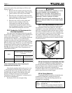
Supply Pressure Minimum Maximum
Natural Gas 5 Inches WC 10.5 Inches WC
(125 mm WC) (265 mm WC)
LP Gas 11 Inches WC 14 Inches WC
(280 mm WC) (350 mm WC)
Table 4. Gas Supply Pressure Requirements
Gas piping must be large enough to provide the
required gas flow rate without excessive pressure drop.
Table 5 specifies pipe sizes which will limit pressure
drop to 0.5 In WC (125 Pa), based on the National
Fuel Gas Code, ANSI Z223.1.
Model
Natural Gas LP Gas
0-50'
(0-15m)
50-100'
(15-30m)
100-200'
(30-60m)
0-50'
(0-15m)
50-100'
(15-30m)
100-200'
(30-60m)
220 1" 1-1/4" 1-1/4" 3/4" 1" 1-1/4"
350 1-1/4" 1-1/4" 1-1/2" 1" 1-1/4" 1-1/4"
Table 5. Required Gas Pipe Size
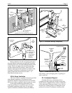
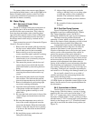
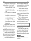
Support gas piping properly so its weight does
not bear on the heater. Install a drip leg, a non-
restrictive shutoff valve and a union on the gas supply
line outside of the heater (see Figure 13).
Before operating the heater, test the gas supply
system, including all connections, for leaks using a
soap solution. Do not use a flame or any ignition
source for leak detection. Disconnect the heater and
its individual gas shutoff valve during pressure testing
if the test pressure is higher than 1/2 psig (3.34 kPa).
If the pressure is 1/2 psig (3.45 kPa) or lower, close
the manual valve on the heater gas control during
testing.