


Page 10
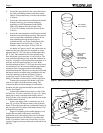
regardless of air density. Good quality combustion and
high efficiency are assured without special adjustment
or changes to the heater.
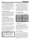
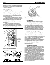
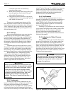
2J. Electric Wiring
2J-1. Electrical Power
The Hi-E
2 requires electrical power from a 115V,
60 Hz source. Wiring connections must be made
exactly as shown in the wiring diagram (See Figure
14). Grounding must be provided as required by the
prevailing electrical code.
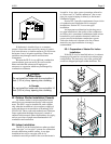
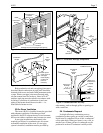
Connect wiring inside the junction box , which is
on the right side of the heater and is accessible through
the door opening. Line voltage connections must be
made within this box. A labeled green grounding screw
is provided in the junction box for a grounding wire
(see Figure 15).
Wiring should include a means to prevent
operation of the heater when there is no water flow.
This is typically done with a time clock “Fireman’s
Switch” as discussed in Section 2J-3.
2J-2. Bonding
The National Electrical Code and most other
codes require that all metallic components of a pool
structure, including reinforcing steel, metal fittings and
above ground equipment be bonded together with a
solid copper conductor not smaller than a number 8
wire. The heater, along with pumps and other such
equipment must be connected to this bonding grid. A
special labeled bonding lug is provided on the right
side of the heater to accommodate this requirement.
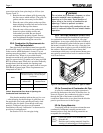
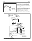
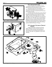
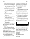
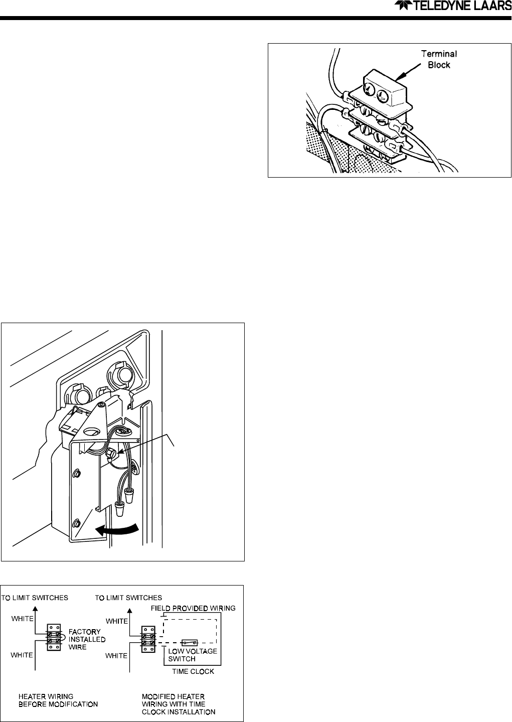
2J-3. Auxiliary Time Clock Wiring
If a time clock is provided to control the pool
filter pump, it should have a separate low-voltage
(Fireman’s) switch for the heater. Route the heater’s
24 VAC control circuit through this switch as shown in
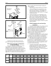
Figures 16 and 17. To do this, remove the “jumper”
from the terminal block in the heater control
compartment. Connect two wires to this terminal block
and route them to the Fireman’s switch at the time
clock. Provide wiring of at least 18 gauge with
insulation at least 3/64" thick and having a temperature
rating of at least 90
o
C.
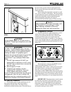
2J-4. Remote Operation
The Hi-E
2 pool/spa heater controls can be wired
for remote operation. Teledyne Laars and Jandy remote
controls are available through the local dealer or
distributor. The CS-02 remote control switches between
the two temperature controllers and turns the heater on
and off. The CS-04 has the same controls as the CS-02
and includes a remote temperature controller.
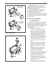
An interrupt (On-Off) type remote control can be
connected by removing the jumper wire on the terminal
block located in the control compartment (see Figure
17) and connecting the two wires from the remote to
the two terminals on the terminal block. This type of
remote control will turn the heater on or off, but will
not switch between the two temperature controllers on
the Flex-Temp control panel.
Figure 17. Terminal Block for Fireman’s Switch or
Remote Control Wiring.
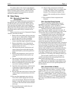
Figure 15. Field Wiring Connections.
ATTACH
GROUNDING
WIRE TO GREEN
GROUNDING
SCREW
Figure 16. Typical Time Clock Wiring.