


Hi-E2
Page 23
such as air conditioning compressors or to an electric
utility company problem. Arrange for correction of the
voltage as appropriate.
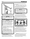
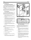
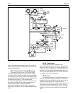
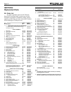
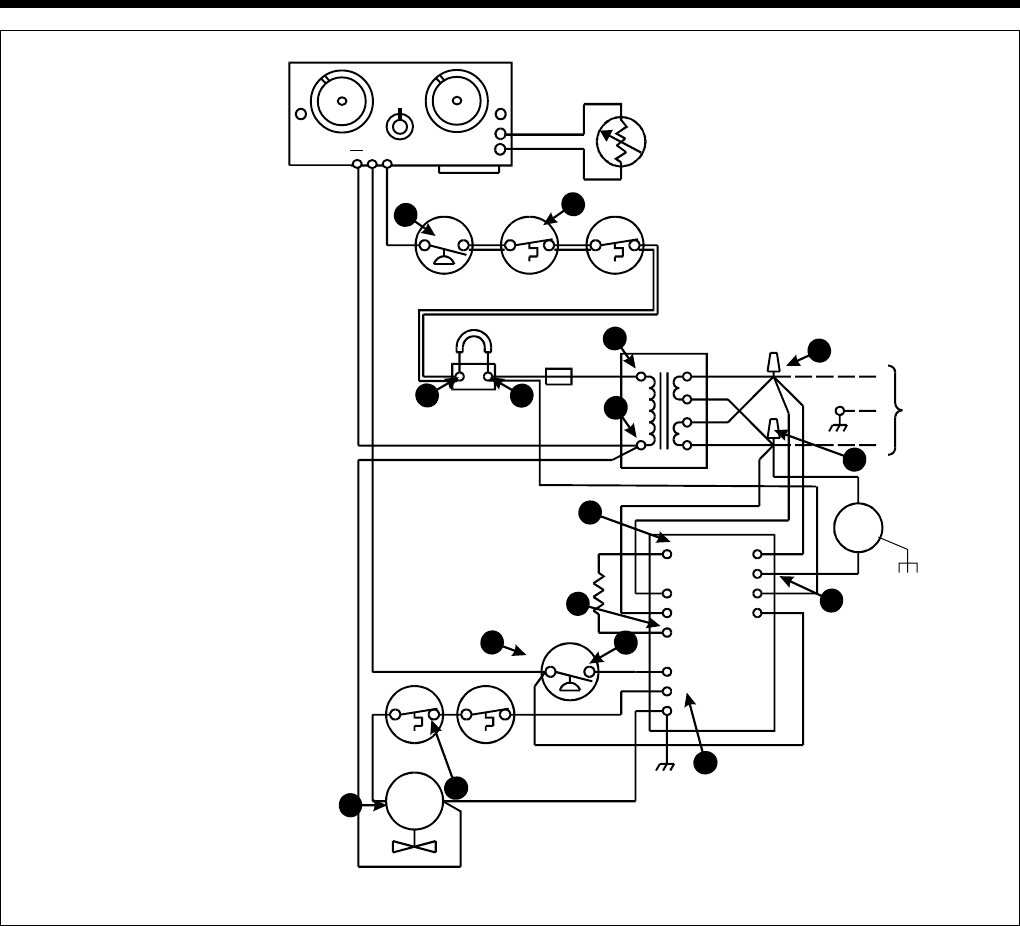
4E-2. Control Circuit Trouble Shooting
The heater controls are in a 24V 60 Hz circuit
with operating and safety controls basically arranged
in a series circuit. Trouble shooting is done by probing
for voltage at various points in the circuit to determine
which component is preventing operation. Check points
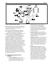
are indicated on Figure 31. The recommended
procedure steps through the circuit in a sequential way,
but verifying voltage at any of the numbered points
confirms that all prior components are OK.
Experienced technicians may be able to shorten the
process by going directly to one of the intermediate test
points.
4E-2a. Transformer
Attach one lead of the voltmeter to the
transformer terminal with a yellow wire attached to it,
which is point 11 on Figure 31. (This lead can be left
in place for most of the testing.) Touch the free lead of
the meter to the transformer terminal with a red wire,
point 1. The meter should show 20-28 volts. If there is
no voltage, replace the transformer.
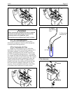
4E-2b. Fuse
Leaving the “common” voltmeter lead in place at
point 11, touch the free probe to point 2. This is the
terminal block screw attached to the red wire from the
in-line fuse, and absence of voltage indicates a
defective fuse. If there is no voltage, inspect the rest of
the wiring to be sure that there is no “short” such as
contact of a terminal with the heater chassis or another
terminal. Correct any such condition and replace the
fuse.
Electronic
Temp
Control
Remote Connector
Water
Temp
Sensor
Pressure
Switch (Water)
OFF
Limit
Limit
Electrical
Fuse
Fireman
Switch
Connection
115V 60Hz
Blower
Igniter
Venturi Pressure
Switch
Vent Limit Burner Limit
(Single Use)
Gas Valve
Ignition
Control
Fenwal
05-33
S120
L1
L2
S2
TH
MVI
G
F1
F2
24V
IND
Y
Y/BK
BR
W
WW
BK
W-BK
Y
Y
Y/BK
Y
Figure 31. Wiring Diagram with Test Points.
Y
(MR)
PR
BR
Y/BK
W
W
BK
N
BK
BK
W-R
R
G
L1
R
W
BK
5
4
32
1
11
A
B
D
C
E
6
7
10
9
24V
IGN
GND
G
8
VAL
IGN/120
8
SPA
POOL
PSW
PV
MV