


5 Maintenance Model 7300A
5-6
Teledyne Analytical Instruments
5.6 Troubleshooting
5.7 General
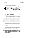
This section contains information on the assembly and the electronic sections
of the Model 7300A Infrared Analyzer. The sample-handling sections of the
system are statistically low failure items and only require the maintenance as
pertinent to sample system operation (plugging, flowrates, leaks, etc.). Flow
system “failures” are usually of the nature that are easily resolved by
personnel familiar with basic mechanics of the Model 7300A flow system or
sample system.
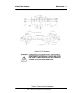
The electronic sections are more complex, requiring the assistance of
personnel trained in electronics in the event of failure. The electronics
sections of the analyzers include advanced solid-state and digital circuitry
which requires a thorough understanding of circuit theory and
troubleshooting techniques.
NOTE
It is recommended that only qualified electronic technicians
troubleshoot electronic failures within the analyzers. Although
both analyzers contain plug-in printed circuit panels, service
personnel should be familiar both with the analyzer theory of
operation and the basics of analog circuit theory before
troubleshooting.
All basic customer electronic adjustments and calibrations of the analyzer
can be accomplished with a DC volt-ohm meter (preferably with a digital
readout). All circuit boards are of the plug-in replaceable type and only
require a DC voltmeter for set-up.
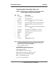
The following is a listing of parts needed for electronic calibration and
troubleshooting of the analyzers:
Accurate DC volt-ohm meter (digital readout) with clip-type leads
Miniature clip-type jumper leads (12" long)
Small blade screwdriver (TAI P/N S-190)