4 Operation Model 7300A
4-30 Teledyne Analytical Instruments
Algorithm setup:
VERIFY SETUP
UP/DOWN to select and
Enter
VERIFY to check whether the linearization
has been accomplished satisfactorily.
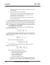
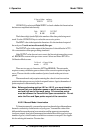
Dpt INPUT OUTPUT
Ø Ø.ØØ Ø.ØØ
The leftmost digit (under Dpt) is the number of the data point being moni-
tored. Use the UP/DOWN keys to select the successive points.
The INPUT value is the input to the linearizer. It is the simulated output of
the analyzer. You do not need to actually flow gas.
The OUTPUT value is the output of the linearizer. It should be the ACTU-
AL concentration of the span gas being simulated.
If the OUTPUT value shown is not correct, the linearization must be correct-
ed.
ESCAPE
to return to the previous screen. Select and Enter SET UP to
Calibration Mode screen.
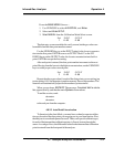
Select algorithm
mode : AUTO
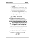
There are two ways to linearize: AUTO and MANUAL: The auto mode
requires as many calibration gases as there will be correction points along the
curve. The user decides on the number of points, based on the precision re-
quired.
The manual mode only requires entering the values for each correction
point into the microprocessor via the front panel buttons. Again, the number of
points required is determined by the user.
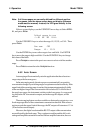
Note: Before performing section 4.8.2 or 4.8.2.3, you must check to
ensure that your calibration gases or points are between low
end and high end of the range setup. All correction points
must be between the Zero and the Span concentration. Do not
enter the Zero and Span points as part of the correction
4.8.2.2 Manual Mode Linearization
To linearize manually, you must have previous knowledge of the nonlinear
thermal-conductivity characteristics of your gases. You enter the value of the
differential between the actual concentration and the apparent concentration
(analyzer output). Analytical Instruments has tabular data of this type for a large
number of gases, which it makes available to customers on request. See Appen-
dix for ordering information. To enter data:


