


3 Start-up and Theory of Operation Model 7300A
3-6
Teledyne Analytical Instruments
3.5 Digital Signal Processing & Electronics
The Model 7300A uses an 8031 microcontroller (Central Processing
Unit—CPU) with 32 kB of RAM and 128 kB of ROM to control all signal
processing, input/output, and display functions for the analyzer. System
power is supplied from a universal power supply module designed (C65507)
to be compatible with any international power source. (See Major Internal
Components in chapter Maintenance for the location of the power supply
and the main electronic PC boards.)
The Temperature Control board (C69535A) is set to a single voltage
(110 or 220 VAC) and set the temperature of the sampling system at 45
o
C.
The signal processing electronics including the microprocessor, analog to
digital, and digital to analog converters are located on the Motherboard
(C67435B) on side of the case.
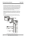
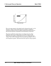
The detector output level depends on the intensity of the IR source, the
length of the cell and the type of fluid in the cell. Usually the output is
between 0.2 and 0.9 mVDC. The Teledyne detector consists of four detec-
tors: A, B, C and D. They are strapped to the inputs of the positive, very
high-gain amplifiers U1, U2, U3, and U4. Amplifiers U1 through U4 are
high quality, very low offset amplifiers.
Preamplified signals (usually between .2 to 1.0 volt) are delivered via
the ribbon cable to the measuring board through an 8-point dip switch.
Connectors deliver power from the measuring board to the amplifiers and
300–450 mADC current to the IR source.
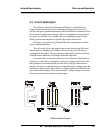
The motherboard serves as a power distribution and interface board.
The Auto-Zero amplifier PCB board is mounted on top of the
Motherboard. These boards are accessible by sliding the system out of the
case after removing the screws on the back plate.
The Temperature Control Board keeps the temperature of the measur-
ing cell regulated to within 0.1 degree C. A thermistor is used to measure the
temperature, and a zero-crossing switch regulates the power of the heaters
inside the sample chamber. The result is a sensor output signal that is tem-
perature independent.
The output of the preamp is fed to variable gain amplifier, which
provides automatic range switching under control of the CPU. The output
from the variable gain amplifier is sent to an 18 bit analog to digital con-
verter.
The digital concentration signal along with input from the control panel
is processed by the CPU and passed on to the 12-bit DAC, which outputs 0-
1 V dc Concentration and Range ID signals. An voltage-to-current converter
provides 4-20 mA dc concentration signal and range ID outputs.