


Infrared Gas Analyzer Start-up and Operation
3-1
Teledyne Analytical Instruments
3.0 Start-up and Operation
3.1 Preliminary
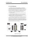
Before applying power to the system, TAI suggests that the electrical
wiring installation be checked against the system input-output diagram.
Proper attention to this preliminary check will prevent severe damage caused
by wiring errors.
Also, verify that all connections to the system have been made
correctly. Refer to the system outline diagram for proper connections.
3.2 NDIR Analyzer Startup
Before power is supplied to the analyzer, TAI recommends the follow-
ing operator’s check be performed:
1. Check for loose or damaged components.
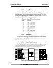
2. Verify that all plug-in circuit cards are firmly seated in their
receptacles.
3. Inspect and verify that all wiring connections are in agreement
with the system Interconnection diagram.
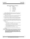
4. Check for correct span gases. (See 4.2: Preparation for Calibra-
tion).
5. Check that sample pressure is regulated to ± .5% of nominal
operating pressure.
6. Check and assure sample remains above dewpoint to eliminate
any condensation from sample tap to return point.
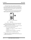
Power up the unit by depressing the rear panel switch. From a first
time power-on warm start attempt, allow (1) one hour warm-up to proceed.
Observe that the Digital display will go through a diagnostic routine before
the readings revert to a continuous concentration readout.
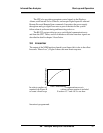
3.2.1 Initial Set-up and Zeroing
Assure the sample will enter from the zero inlet gas position. Open the
zero gas tank and set the pressure regulator to 20 psig. Set the zero gas flow