


Infrared Gas Analyzer Operation 4
4-11
Teledyne Analytical Instruments
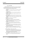
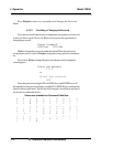
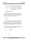
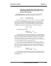
Dpt INPUT OUTPUT
Ø Ø.ØØ Ø.ØØ
The leftmost digit (under Dpt) is the number of the data point being moni-
tored. Use the UP/DOWN key to select the successive points.
The INPUT value is the input to the linearizer. It is the simulated output of
the analyzer. You do not need to actually flow gas.
The OUTPUT value is the output of the linearizer. It should be the ACTU-
AL concentration of the span gas being simulated.
If the OUTPUT value shown is not correct, the linearization must be correct-
ed.
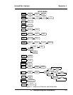
ESCAPE
to return to the previous screen. Select and Enter
SET UP to
Calibration Mode screen.
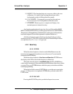
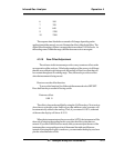
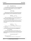
Select algorithm
mode : AUTO
There are two ways to linearize: AUTO and MANUAL: The auto mode
requires as many calibration gases as there will be correction points along the
curve. The user decides on the number of points, based on the precision re-
quired.
The manual mode only requires entering the values for each correction
point into the microprocessor via the front panel buttons. Again, the number of
points required is determined by the user.
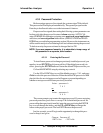
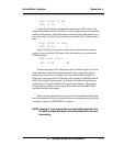
4.3.8 Troubleshooting information
Accessing the HARDW_VAR function will allow a qualified technician
to get further information on the health of the analyzer. This is a complimentary
troubleshooting tool to SELF-TEST. Information displayed in the VFD display is
shown below:
Calib_factor = 5.00 (This is the slope calibration value of the span,
default is 5.00)
AtoD_ave = 1289 (This is the raw ADC count, -262144 to
262143 are acceptable raw counts but must still
be evaluated by knowing what gas is flowing
through the analyzer)
lOffset[r][g] = 492 (This is the current zero offset from the zero
calibration of the gain and range the instrument is
on at the moment. It should be between
10,000 to 10,000)