


Infrared Gas Analyzer Installation 2
2-3
Teledyne Analytical Instruments
2.2.4 Pipe Connections
Refer to Appendix Piping Drawings for information about pipe connec-
tions. On special systems, consult the text in the manual that describes your
particular sample system in detail.
2.2.5 Sample Delivery System
The sample delivery system should be designed to operate reliably and
must be of large enough capacity to avoid flow stops. A pump is required only
if there is insufficient pressure to reliably supply the sample to the system
equipment panel. Do not complicate the delivery system by adding a pump
unless it is absolutely necessary. If a pump is required, select a type that can
handle the sample (corrosion), as well as meet the area classification and
Environmental conditions.
2.2.6 Venting the System
In gas analysis systems, the system vent manifold or bypass/sample vents
must terminate in a safe area as the sample may be poisonous, corrosive or
flammable.
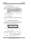
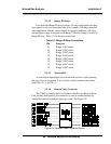
2.3 Electrical Connections (Rear Panel)
Figure 3-3 shows the Model 7300A rear panel. There are connectors
for power, digital communications, and both digital and analog concentration
output.
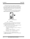
For safe connections, no uninsulated wiring should be able to come in
contact with fingers, tools or clothing during normal operation.
CAUTION: Use Shielded Cables. Also, use plugs that provide
excellent EMI/RFI protection. The plug case must be
connected to the cable shield, and it must be tightly
fastened to the analyzer with its fastening screws.
Ultimately, it is the installer who ensures that the
connections provide adequate EMI/RFI shielding.